background image

OCT-16 


PAGE 11 


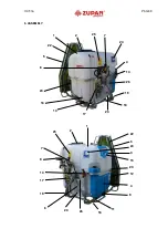
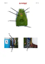
1.  Tank made of polyethylene with a scale divided in 10 l. 
2.  Tank lid with basket filter.  
3.  Clear water tank for hand washing 
4.  Clear water tank for system cleaning and thinning of technical leftover 
5.  Air deflector with a fan D.700. 
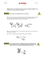
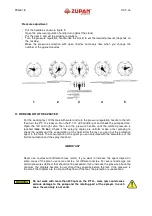
6.  Pump AR 1064 with a safety valve. 
7.  Remote control with manometer. 
8.  Command box 
9.  Sucking filter.  
10.  Pressure filter. 
11.  Ball valve for system washing tank. 
12.  Clutch for idle run. 
13.  Valve for emptying the tank.  
14.  Ball valve in return circle. 
15.  Clean water tank pipe. 
16.  Tank mixer  
17.  Valves (stirrer, powder mixer) 
18.  Frame of the sprayer. 
19.  Three point connection. 
20.  Transmission. 
21.  Fan. 
22.  Nozzle holder with anti drop valves and ceramic nozzles. 
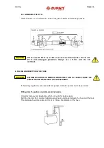
23.  P.T.O. support 
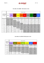
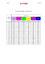
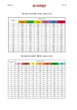
24.  Spray rate chart. 
25.  Warning sticker. 
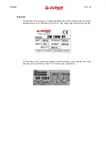
26.  Type plate. 
27.  Adjustable air deflector 


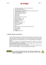
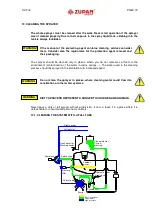
6. WORKING PRINCIPE OF THE SPRAYER 


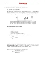
The protection agent flows from the tank through the sucking filter to the pump and from pump 
under  high  pressure  through  the  pressure  filter  to  both  spraying  sides.  With  the  pressure 
regulations valve you can regulate the pressure with the turn the pressure regulation handle to 
the right (clockwise) to increase the pressure, or to the left (counterclockwise) to decrease the 
pressure. 
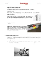
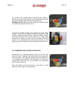
Before you run the sprayer, turn the regulation handle to the left, so that there is no pressure 
on the manometer. When you have working rpm, turn the handle to the right so long, that you 
achieve the wanted pressure on the manometer 
When the nozzles are closed, all fluid is returning to the tank, when they are operating, a part 
of the fluid is for spraying and a part returned in the tank.  
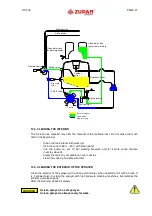
Tank mixers must be always on, to secure the homogeneity of the protection agent. When the 
level of the fluid sinks under 20 l, you must close them to prevent foaming.    


Do  not  work  with  pressure  above  15  bars.  With  to  high  pressure  the 
efficiency of  spraying sinks. For a higher range of droplets, increase the rpm 
of the fan, not the pressure!  


 WARNING !


Summary of Contents for ZM 400 VCRA

Page 1: ... www zupan si E Mail zupan maribor siol net Št reg 1 1357 00 Okr sod v Mariboru mat št 5332338 osn kapital 111 733 00 Operator s manual Carried sprayer ZM 400 500 600 VRA VCRA Before starting operation please carefully read and adhere to this instruction manual and safety advice Improper use can result in damage to people animals environment or the machine Keep for future users ...

Page 2: ...R OF THE SPRAYER 21 13 CALCULATING THE AGENT CONSUMPTION ON A HECTARE 22 13 1 DEFINING THE RIGHT SPEED 22 13 2 DEFINING THE FLUID CONSUMPTION ON A HECTARE 22 13 3 DEFINING THE CONCENTRATION 23 14 OPTIMAL WORKING SETTINGS 27 15 PREPARING THE SPRAYER FOR LOW TEMPERATURES 28 16 PUMP MAINTENANCE 29 17 OPERATIONAL PROBLEMS OF THE SPRAYER 34 18 NOZZLE HOLDER 35 19 FAN DRIVE 35 20 MIXING THE FLUID IN THE...

Page 3: ...ries VRA and VCRA we can protect the plants a Sprinkle 800 1500 l ha b Spraying Rough spraying 400 800 l ha Fine spraying 100 400 l ha Very fine spraying do 100 l ha only with electrostatic In modern plant protection we rarely use high amounts of water 800 1500 l ha because it is uneconomical the loss of the protection agent is enormous The droplets combine and flow of the leaf by 1500 l ha almost...

Page 4: ...hat 2 Avoid the contact between skin and toxic mediums 3 When you work with toxic mediums always be sure that you have near clear water and that clean water tank is full 4 Do not leave the toxic mediums or they package outside or in rooms where they are in reach of children or unauthorized persons 5 Equipment used for toxic mediums should never be used for work with food drinks and clean water we ...

Page 5: ...hydraulic components are moving do not be in their working area Danger of squeezing between the machine and the load when it is oscillating Do not stay near the P T O injuries possible Do not go into the tanks TOXIC DANGER rotating parts do not reach with your hands near the fan Ejected parts Keep distance to the fan whilst the tractor is running and fan is rotating ...

Page 6: ...th rotating heads or for can washer Ball valve for hydraulic stirrer Ball valve for hydraulic stirrer Release valve to release the fluid from the tank 3 way ball valve on the return circle Never change position when the P T O is working Position for system cleaning Closed do not use Normal work position WARNING ...

Page 7: ...xan Mudecan Elancolan and Teridox can cause damage to the pump diaphragms hoses spray lines and tanks Therefore prolonged stay of pesticides in containers pump and spray system for more than 15 hours is prohibited When using such aggressive plant protection products the immediate spreading of the spray mixture and the subsequent rinse with clean water is recommended In particular we warn against u...

Page 8: ... information of the manufacturer the model production year max revolutions of the P T O max work pressure and serial number On the pump is also a plate that indicates the manufacturer serial number max work pressure max revolutions of the P T O and the max fluid stream ...

Page 9: ...OCT 16 PAGE 9 5 ASSEMBLY 1 2 7 8 14 9 15 11 18 5 3 17 4 6 12 19 20 22 23 24 25 26 1 18 2 4 14 16 17 5 7 23 13 22 20 8 19 25 24 26 ...

Page 10: ...PAGE 10 OCT 16 1 18 22 5 27 21 12 20 10 ...

Page 11: ...rough the sucking filter to the pump and from pump under high pressure through the pressure filter to both spraying sides With the pressure regulations valve you can regulate the pressure with the turn the pressure regulation handle to the right clockwise to increase the pressure or to the left counterclockwise to decrease the pressure Before you run the sprayer turn the regulation handle to the l...

Page 12: ...h the operating with the sprayer but make it as written in the manual described We recommend the next steps 1 Connect the sprayer 2 Control if it is working properly 3 Fill the tank with water 4 Turn the P T O on and check if the pump and the pressure unit are working properly 5 Check all connections and nozzle holders 6 Turn the P T O off 7 Clean the sucking and pressure filter 8 Make a test spra...

Page 13: ...ld turn over danger for people and the machine When the sprayer is being lifted or lowered make always sure that no one is near the machine 1 5m if not so someone could get hurt When the sprayer is being connected consider the whole weight of it In general it is recommended 1 Putt weights on the front of the tractor 2 Increase the pressure in the tires consider the tractors manual 3 Drive slowly e...

Page 14: ...he P T O grease the inner tube and make sure that the tubes are fitting well together Cut the plastic protection tube 20 mm more than the steel tubes When you are connecting the P T O to the tractor and pump make sure that it moves free that there are no obstacles When the P T O is working the angle should not be more than 15 degrees For the personal safety it is important that the plastic protect...

Page 15: ... THE TANK EXTREME CAUTION IS NEEDED WHEN THE TANK IS FILLED FROM THE PUBLIC WATER NETWORKS OR WATER DAMS If the safety regulations are unconsidered people animals or plants could be poisoned Filling from the public or private water networks Consider the laws and regulations which are valid for water supply By filling the tank from a water network always have a distance between the hose and the tan...

Page 16: ...the suspension while working on slopes Emptying the tank Rotate the red handle of the ball valve on the lower part of the tank see photo Putt a vessel under the outlet which will hold the fluid then turn the red handle to empty the tank After total emptying the tank turn the handle back in the work position 10 HOW TO USE THE REMOTE UNIT The one hand unit BY MATIC is used to engage the pressure and...

Page 17: ... The left side is open 3 The left and the right side are open 4 The right side is open 5 Left and right side closed the pump is on the adjusted pressure In this position the powder mixer can be used and the tank mixer ...

Page 18: ...ying angles are uniform make a test spraying to check the quality and the consumption of the fluid After the test you can put the protection agent in the tank The consumption of the agent you can calculate with the calculators of the fluid consumption and the spray rate chart IMPORTANT Never use nozzles with different holes color If you want to increase the agent deposit in some areas of the plant...

Page 19: ...ns cleaning advices consider them Consider also the region laws for the protection agent removal and their packaging The sprayer should be cleaned only in places where you do not represent a threat to the environment contamination of the water in wells springs The water used in the cleaning process should be sprayed in the plantation with increased speed Do not clean the sprayer in places where cl...

Page 20: ...the clean water tank is empty Close the mixers too When you finish turn the handles in their first position This procedure cleans the system enough so that there will not be any problems when the work will be continued 12 2 REMOVING THE TECHNICAL LEFTOVER We consider as a technical leftover the fluid in the tank that cannot be used because of the tank shape fluid in the pump hoses and filters The ...

Page 21: ... THE EXTERIOR OF THE SPRAYER Clean the exterior of the sprayer with a strong jet of water when needed rub it with a brush It is it allowed also to clean the sprayer with high pressure cleaning machines but watches the stickers and plastic parts After the cleaning check all screws A clean sprayer is a safe sprayer A clean sprayer is always ready for work WARNING Left nozzles Clean water tank for sy...

Page 22: ...eal speed Driving speed can be calculated with formula s V 3 6 t V Driving speed in Km h s Travelled distance m t Time used for driving on this route Sec Thus speed of the tractor with used 72 seconds for 100 m distance will be 100 V 3 6 5 Km h 72 13 2 DEFINING THE FLUID CONSUMPTION ON A HECTARE On the sprayers ZM there are ceramic nozzles serial the working pressure for them is between 6 and 15 b...

Page 23: ...les violet green red can be calculated if you want to change quantity of the used fluid 13 3 DEFINING THE CONCENTRATION The normal consumption for calculation of the concentration is 1500 l ha By concentration of 0 2 of an agent you must use 3 kg of it per hectare By reducing the fluid consumption from 1500l ha to 500l ha then must raise the concentration for 3 times From the experiences we know t...

Page 24: ... 1 91 2 08 2 44 2 78 3 37 11 0 39 0 53 0 69 1 07 1 40 1 99 2 17 2 55 2 90 3 52 12 0 41 0 55 0 71 1 11 1 46 2 07 2 26 2 65 3 03 3 66 13 0 42 0 57 0 74 1 15 1 51 2 15 2 35 2 75 3 14 3 80 14 0 44 0 59 0 77 1 19 1 57 2 22 2 43 2 85 3 26 3 93 15 0 45 0 61 0 78 1 23 1 62 2 30 2 51 2 94 3 36 4 06 Working pressure in bar Flow in l min violet olive orange green yellow blue red 1000620501 1000620502 1000620...

Page 25: ...0 55 1 10 1 46 1 83 2 19 11 0 38 0 57 1 15 1 53 1 91 2 30 12 0 40 0 60 1 20 1 60 2 00 2 40 13 0 42 0 62 1 25 1 67 2 08 2 50 14 0 43 0 65 1 30 1 73 2 16 2 59 15 0 45 0 67 1 34 1 79 2 24 2 68 16 0 46 0 69 1 39 1 85 2 31 2 77 17 0 48 0 71 1 43 1 90 2 38 2 86 18 0 49 0 73 1 47 1 96 2 45 1 94 19 0 50 0 75 1 51 2 01 2 52 3 02 20 0 52 0 77 1 55 2 07 2 58 3 10 21 0 53 0 79 1 59 2 12 2 65 3 17 22 0 54 0 81...

Page 26: ...0 0 92 1 39 1 85 2 31 2 77 3 70 18 0 0 98 1 47 1 96 2 45 2 94 3 92 20 0 1 03 1 55 2 07 2 58 3 10 4 13 Flow table of the ALBUZ AMTP 80 nozzles in l min Pressure in bar Flow in l min 0 8 1 0 1 2 1 5 2 0 2 3 2 5 2 0 23 0 32 0 48 0 65 0 91 1 17 1 61 3 0 28 0 38 0 58 0 78 1 09 1 41 1 94 4 0 32 0 44 0 66 0 89 1 25 1 61 2 21 5 0 36 0 48 0 73 0 99 1 38 1 78 2 45 6 0 39 0 52 0 80 1 07 1 50 1 94 2 67 7 0 42...

Page 27: ...m 3 0 m max 4 5 m 3 5 m Fan shape VCRA O 75 000 m h min 3 0 m 4 0 m 4 5 m 5 0 m max 6 0 m 6 0 m Round fan shape VCRA H 75 000 m h min 3 0 m 8 0 m 5 0 m 7 5 m max 8 0 m 7 0 m Set the optimal working position of the nozzles in the plantation with the highest culture for the lower cultures just close the upper nozzles Help You need for the settings measuring stick length 4 m measuring tape 2 m scotch...

Page 28: ...metrical left right to adopt to the height Check again the spraying height Check sprayer before each spraying season on its dosage and distribution accuracy 15 PREPARING THE SPRAYER FOR LOW TEMPERATURES For low temperatures you must prepare the sprayer under 0 degrees C stored outside so that cannot be damaged because of frost Hoses Check the hoses for damages make sure that they are not squeezed ...

Page 29: ...the fan with a brush so that there are no dirt or agent leftovers The dirt can unbalance the fan vibrations which can break some parts of the sprayer Clean also the deflector 16 PUMP MAINTENANCE Before the spraying 1 Oil control When the shaft is disengaged the oil level must be on the marked place If the oil should be refilled use SAE 20 W 40 oil 2 Do not engage the pump if the sucking filter is ...

Page 30: ...he valve to close the valve the safety valve is now working again as in the beginning Pump valve control Before ever season or after a season check the valves and O seals on the valves Check the valves also if the pump is not working properly Proceed in these steps a Unscrew the valve cover b Remove the cover c Pull the O rings and valves from the housing d Check the valves and O rings Check speci...

Page 31: ...nging oil b Unscrew the head of the pump change the membranes successively c Remove the head of the pump d Unwind the screw which connects the membrane and the piston e If one membrane is broken clean the housing with petrol f If some membrane is broken check the guidance for cracks or sharp edges If necessary replace them g Place the membranes and the pump heads but pay attention to their positio...

Page 32: ...valve seats and clean them 2 The manometer is oscillating The pump is sucking air or the air is still in the pump Check the suction system Open the pressure valves on the operating unit and leave the pump working Check the pressure in the air chamber 3 The water flow is irregular The air chamber is empty Raise the pressure in the chamber for 1 10 of the working pressure 4 The water is flowing with...

Page 33: ...OCT 16 PAGE 33 ...

Page 34: ...e hydraulic mixing Check the valves and their wear Change the manometer Pressure drop Dirty filters Wear nozzles The valve on the tank lid stuffed up Air sucking while you have few fluid in the tank Clean all filters and system with clean water When working with powder agents check if the hydraulic mixer in on Check the nozzle flow and if it is deviating more than 10 change them Close the valve of...

Page 35: ...made from oxide ceramic and are very resistant to usage but they must be cleaned with a brush toothbrush and clean water or alcohol Do not use sharp objects for cleaning and do not let them fall The membrane valves must be changed when the fluid is dropping more than 10 seconds after closing the main valve Even small damages can change the spraying picture Do not turn the nozzle holders when press...

Page 36: ...the fitting fork out and then pull the mixer out from stirrer s body Watch the seals when you put it together again 21 SUCKING FILTER The sucking filter protects the pump from hard particles It is placed under the tank Cleaning of the filter Before you dismantle the filter put a bucket under it to catch the fluid Make sure that no fluid is in the tank or close the valve near the filter on the pict...

Page 37: ...n also use a soft brush While putting it together watch the O rings Empty the filter before the winter 23 POWDER MIXER The powder mixer is in the net in the tank We install two types the candle and the mushroom They are used to mix powder protection agents How to use the mixer Fill half of the tank with water Put the powder in the net Close the lid carefully Put the P T O and the pump on Move the ...

Page 38: ... T O and try it again Never change gears while the P T O is working 25 SPRAYER LUBRICATION Check the oil in the gearbox regularly because the load on it is very high The level of the SAE 90 oil can be checked in the glass window on left side of it The level should be in the middle of the window The oil can be refilled through the hose above it After the first 200 working hours it is recommended to...

Page 39: ...ed also between the suction hose and the pressure unit but there you need an accessory 1 2 on 1 and one 3 4 on 1 Measuring the flow on the nozzles You need a soft hose with an inner diameter of 20 mm a measuring jug and a stopwatch The procedure Pull the hose over the measured nozzle Close all other nozzles Set the working pressure Leave the fluid flow 60 seconds into the jug Compare the measured ...

Page 40: ...e in agent tank 400 500 600 l Clear water tank for hand washing 17 l Clear water tank for system washing 50 l Technical leftover Technical leftover that can be watered 3 0 l Technical leftover that cannot be watered 1 8 l Maximal working angle 30 Nozzle number 14 Pump Producer Annovi Reverberi S p A Italy Pump type AR 1064 C SP Maximal volume flow 105 l min Maximal pressure 50 bar Maximal rpm 540 ...

Page 41: ...ash inch 0 73 mm Pressure net 50 mash inch 0 50 mm Needed tractor power by 540 rpm min and 15 bar VRA 18 kW VCRA 36 kW WARRANTY Look added page SERVICE ZUPAN d o o Celestrina 3 2229 MALEČNIK Tel 02 471 60 50 471 60 54 Fax 02 471 60 51 http www zupan si E MAIL zupan maribor siol net ...

Page 42: ...ing the left and right nozzles Control unit assembly 1 Pressure regulation valve for adjustment of working pressure 2 Solenoid valve for opening and closing left and right nozzles 3 Pressure gauge 4 By pass 5 Pressure filter 6 Additional ball valve for hand spraying 7 Diodes they are lightening when the valve is open 8 Command box with switches for opening and closing of solenoid valves 1 3 4 2 5 ...

Page 43: ...OCT 16 PAGE 43 28 2 ELECTRIC VALVES WITH PRESSURE REGULATION 2 6 4 3 1 8 18 19 7 12 9 13 14 15 15 16 16 21 20 11 10 17 ...

Page 44: ... the left or the right side for closing and opening the fourth group of nozzles optional or for opening and closing of airstream 17 30pin connectors with connection cable 18 Solenoid valves 19 Pressure filter 100 mash inch optional 20 Pressure switch 21 Central switch The Solenoid valves can be used in Orchard and Vineyard The Software controls the distribution of pesticides to both sides of the r...

Page 45: ...through items selected item is indicated by a black line B Press to open the selected menu item The three dots under an item indicate presence of another setup menu EDITING A VALUE A Press to move through digits B Press a few times to edit the highlighted digit C Press to confirm The display goes back to previous page D Press to exit page without confirming modification Edited value must fall with...

Page 46: ...Level correction Only one of the two items will be displayed depending on set operating mode 28 1 2 LANGUAGE Open language setting menu Setup menu Options Language The display will show the current setting below the selected item Press OK to select the language 1 Select a language through key 1 2 Press OK to save or ESC to quit without saving ...

Page 47: ... current setting below the selected item Press OK to select flow rate unit of measurement 1 Select a unit through key 1 2 Press OK to save or ESC to quit without saving VOLUME UNITS OF MEASUREMENTS Open volume unit of measurement setting menu Setup menu Options Units of measurem Volume The display will show the current setting below the selected item Press OK to select volume unit of measurement ...

Page 48: ...measurem Pressure The display will show the current setting below the selected item Press OK to select pressure unit of measurement 1 Select a unit through key 1 2 Press OK to save or ESC to quit without saving DISPLAY CONTRAST Open display contrast menu Setup menu Options Display contrast The display will show the current setting below the selected item Press OK to edit the selected menu item ...

Page 49: ...ble alarms Open Alarm tones menu Setup menu Options Alarm tones The display will show the current setting below the selected item Press OK to edit the selected menu item 1 Set status through key 1 2 Press OK to save or ESC to quit without saving KEYTONES Open Alarm tones menu Setup menu Options Alarm tones The display will show the current setting below the selected item Press OK to edit the selec...

Page 50: ...me way The display will show the current setting below the selected item Press OK to edit the selected menu item 2 To activate the alarm press keys above at the same time until message OFF goes off and pressure alarm value is displayed instead Carry out the same procedure to disable alarm again 3 Set alarm value A Press to move through digits B Press a few times to edit the highlighted digit C Pre...

Page 51: ...ted item Press OK to edit the selected menu item 2 To deactivate the alarm press above shown keys at the same time until the set value disappears and the message OFF is displayed instead Carry out the same procedure to enable alarm again 3 Set alarm value A Press to move through digits B Press a few times to edit the highlighted digit C Press to save changes or D Press to quit the page without con...

Page 52: ... the selected item Press OK to edit the selected menu item 2 To activate the alarm press above shown keys at the same time until the message OFF goes off and the alarm value is displayed instead Carry out the same procedure to disable alarm again 3 Set alarm value A Press to move through digits B Press a few times to edit the highlighted digit C Press to save changes or D Press to quit the page wi...

Page 53: ... Setup menu Test Display Press OK to perform the test All pixels on display are turned on Press ESC to go back to previous page KEYS TEST Keys test checks the device keys correct operation Open keys test menu Setup menu Test Keys Press OK to perform the test 1 Press any key and the corresponding display area will turn on 2 Press ESC to quit as soon as you acknowledge the switch on of the correspon...

Page 54: ...e electric valves Place the command box in the tractor so that you can reach all switches and see the control lights Plug the box to the tractors electric network Turn the pump on With the pressure regulation switch 11 set the working pressure Compare the pressures on the manometer 3 and on the display 10 they must be equal Open the left and the right spraying side with the main switch 12 and open...

Page 55: ...ith this accessory you can set the spraying angle and so adjust the spraying range The range depends also on the working pressure and the diameter of the nozzle the greater the diameter the greater the range Nozzle flow in l min Nozzle diameter Pressure in bar 7 10 15 20 1 0 1 3 1 6 1 9 2 2 1 2 2 0 2 4 2 9 3 4 1 5 2 4 2 8 3 4 3 9 1 8 2 8 3 3 4 1 4 7 2 0 4 1 4 9 5 5 5 9 ...

Page 56: ...al 111 733 00 Declaration of conformity The undersigned ZUPAN d o o Celestrina 3 2229 MALEČNIK Slovenia Declares under its own responsibility that the machine Sprayers series VRA VCRA Complies with the requirements established by directive 2006 42 EC and conforms to provisions of the following harmonized standards EN ISO 12100 EN 12761 1 EN 12761 3 Person to create the technical documentation ZUPA...

Page 57: ...in the machine 2 Technical personnel will undertake the necessary repairs in the minimum time possible compatible with organisational needs 3 To take any claim under the warranty this certificate of warranty fully compiled bearing the dealer s stamp and accompanied by the invoice or receipt showing the date of purchase must be displayed to the personnel authorised to approve work 4 The warranty sh...

Reviews: