background image

Figure  4-­14


Camera  search  interface  


Click  the  button  

ˈ

Pop-­up  camera  selection  screen  shown  in  Figure  4-­15,  the  

interface  device  selection,  choose  the  camera  finished,  click  Apply  determine  the  
choice.  
Need  to  remove  the  management  camera  in  the  camera  list,  click  the  check  box

,  

Select  the  camera,  the  camera  button  and  then  click  Delete  to  remove.  

Area  6

˖

Configure  network  camera.  

You  can  view  the  status  of  the  network  camera,  set  the  name  of  the  network  cameras,  
IP  address,  video  strategy,  stream  parameters,  and  motion  detection  parameters.  

z


View  the  status  of  network  cameras,  status:  online,  not  online,  account  errors.  

Online  equipment,  you  can  click  

   Real-­time  video  preview.  

z


Modify  the  name  of  the  network  camera.  
Enter  the  desired  name  of  the  device  corresponds  to  the  name  of  the  bar,  you  can  
modify  the  name  of  the  camera.  

z


Modify  the  IP  address  of  Network  Camera.  

4.


Click  to  modify  the  IP  address,  network  cameras  IP  Settings  dialog  box  pops  up  

5.


Set   the   network   camera   IP   specific   operation   methods   and   procedures,   see   the  
"Network  Video  Recorder  User  Manual  in  8.1.5  Network.  

z


Set  video  strategy.  

1.


Video  strategy  information,  click  on  the  desired  modifications  configuration  dialog  
pop-­up  video  strategy

˗


2.


Specific   methods   of   operation   and   the   steps   set   video   strategy   see   8.1.7   Video  
Network  Video  Recorder  User  Manual.  

19  

z


Set  the  device  stream.     

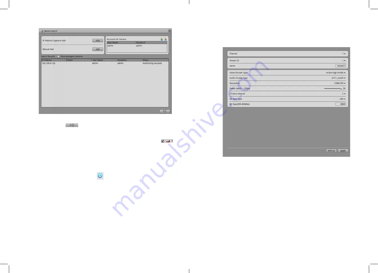
1.


Click   stream   information   required   to   modify   the   pop-­up   the   stream   configuration  
dialog  box  shown  in  Figure  4-­15  will  show.  

Figure  4-­15


stream  quick  configurations  


2.


Applied   to   all   of   the   same   device   switch   stream   is   set   to   open,   click   the   Apply  
button   will   automatically   set   the   current   parameter   to   all   devices   with   the   same  
resolution  parameters.  

z


Set  to  detect  alarm.  

1.


Click   the   desired   modification   motion   detection,   motion   detection   alarm   dialog  
pops  up.  

2.


If  the  motion  detection  alarm,  you  must  set  the  arming  time  and  detection  area.

20  

Summary of Contents for N41080P-H4P-BK

Page 1: ...age within the product s enclosure that may be of sufficient magnitude to constitute a risk of electric shock The exclamation point within an equilateral triangle is intended to alert the user to the presence of important operating and maintenance servicing instructions in the literature accompanying the appliance WARNING TO PREVENT FIRE OR SHOCK HAZARD DO NOT EXPOSE THIS UNIT TO RAIN OR MOISTURE ...

Page 2: ...ext Special Notices When using video surveillance products comply with applicable statutory and regulatory requirement to enable and maintain legal surveillance device It is illegal for company or person to install surveillance devices in an office to monitor employees outside scope of local law or use surveillance devices to invade other people s privacy with illegal purposes i Contents About thi...

Page 3: ... Playback 50 10 5 Alarm Search 52 10 6 NVR setup 52 10 7 Network Camera setup 53 11 NVMS Access NVR 54 11 1 Start and Run 54 11 2 Login 54 11 3 System main interface 55 11 4 NVR management 55 11 5 Playback 63 12 F A Q 66 iii ...

Page 4: ...evice checking the environment according to the Table 1 1 Installation environment check items Check item standard Moisture resistant The relative environment humidity must be in the range from 5 to 95 If the humidity is higher than 95 a dehumidifier must be installed such as an air conditioner with the dehumidification function or a dedicated Dehumidifier In addition water seepage water dropping ...

Page 5: ...resolutions Output DVI I interface to transition through the first converted to VGA or HDMI output Supplied with DVI to VGA converter And DVI to HDMI converter Storage 3 HDD Two external swappable hard disk maximum 2x4TB hard drive supported Audio In Out 3 5mm linear audio output Audio formats G711_AˈG711_U Network Transmission control Embedded network bandwidth adaptive flow control technology In...

Page 6: ...icated network topology shown in Figure 3 1 Figure 3 1 camera dedicated network 5 4 Installation 4 1 Hard disk recommended Given the current market of different brands the uneven quality of the different models of hard recommended to use Seagate or Western Digital brands which are designed for security server applications offering 24x7 reliable operation 4 2 Days recorded Table 4 1 video storage t...

Page 7: ...1 shows the description of front panel Figure 4 5 Front panel Table 4 1 Front panel description No Name Description 1 Power indicator ON OFF key Open close NVR NVR is turned on the power light is solid red power light off means NVR Close 2 Network LAN LED LAN normal solid Green status Data transmitting flashing status 3 USB interface For connecting external mouse keyboard mobile hard disk 4 HDD da...

Page 8: ...ST button Restores the factory default settings 5 second holds 9 GND connect GND connect 10 DC48V Power interface DC48V 1 04A power input 4 6 First boot z Make sure that the right of access to power NVR z Ensure correct display HDMI or VGA interface connection is set from switch If the front panel of the power indicator lamp does not flash please plug in the power cable Enable the power switch NVR...

Page 9: ...ectly through the rear panel power off switch cut off the power or unplug the power cord should be avoided z In some circumstances the power supply is not normal will lead to the NVR not to work properly serious damage can occur to the NVR In this environment it is recommended to use regulated power supply or a backup AC source z If the device is logged into the main interface you can click the to...

Page 10: ... step tuning 3 Use UP DOWN LEFTRIGHT button to adjust the screen Step 4 Click the configuration interface to close Exist displayer interface Back to Login interface 13 4 9 Add Network cameras This NVR allow to connect maximum16 pcs network cameras Recording baud rate totally is 24Mbps and live video totally baud rate is 24Mbps z NVR maximum support to connect 16 pcs D1 resolution with average bard...

Page 11: ...guration fast configuration of the features of the camera network configuration stream configuration motion detection configuration Enter the rapid configuration interface as shown in Figure 4 11 Figure 4 11 Fast configuration interface The rapid configuration interface description Area 1 NVR Basic information and time synchronization functions z NVR Basic information configuration The NVR can set...

Page 12: ...equipment networkd Area 4 Hard disk managementDŽ z Format the hard disk will cause video loss please use this feature with cautiond z Power until off to remove the hard drive use the software to control this process as below otherwise it may cause damage to the hard disk recordings Hard disk management for hard disk management NVR z Format hard disk Click the Format button pop up prompts choose to ...

Page 13: ...of Network Camera 4 Click to modify the IP address network cameras IP Settings dialog box pops up 5 Set the network camera IP specific operation methods and procedures see the Network Video Recorder User Manual in 8 1 5 Network z Set video strategy 1 Video strategy information click on the desired modifications configuration dialog pop up video strategy 2 Specific methods of operation and the step...

Page 14: ...reams in current camera And after we switched the streams by the bottom line of the live video window we will see the stream information Live video interface introduction as Figure 4 16 Table 4 3 Live video interface introduction Items Name Content 1 Top menu Click Live video Recording playback Alarm search and Quick setup to enter the responding interface Click icon to check the HDD information C...

Page 15: ... enable the full screen function also the time delay for full screen showing When this function is enabled if we didn t do any actions during the delay time period then it will go to the full screen mode immediately When it is in full screen mode after you moved the mice to the bottom line it will give out the tool bar click the icon in tool bar we can exit the full screen mode Then you click can ...

Page 16: ...t playback video time The playback video will be displayed above the time axis blue marked means retain video red marked means alarm video yellow means label video green means normal video You can input the time After clicked the playback video will jump to the pointed time After the time zone you can select the time interval 15 minutes 30 minutes 1 hour 4 hours 8 hours 12 hours 1 day When 1 hour ...

Page 17: ... the backup file options z Backup file large size we can define the maximum size of individual file z Create the subdirectories can be specified create the directories based on the network cameras IP or ID z Whether to combine video clip you can specify whether to make two discontinuous video merged into one file Step 3 Select backup recording Method one We can select the recording and backup duri...

Page 18: ... alarm information from left list Means this camera have alarm information Step 8 We can select the alarm type at the Type drop down menu Figure 4 25 Alarm searching interface Step 9 Date selections You can choose the date period which you want to search in the calendar area Click ǃ to switch the month click ǃ to switch month Means the date which has been selected If it is red color then it means ...

Page 19: ...kup button to make backup files 31 9 Setup Setup includes NVR setup and camera setup NVR setup for NVR configure and camera setup for cameras configure 9 1 NVR setup Click NVR setup in upper right to inter the NVR configure interface show in Figure 4 26 Figure 4 26 NVR setup 9 1 1 Device information When inter NVR setup interface we can see the system information show in Figure 4 26 Device informa...

Page 20: ...ameras like below Step 13 Click the add button to call the camera searching interface like Figure 4 27 Step 14 Add the cameras according to the IP segment or something specific z Add IP address 4 Click Add button in IP address to call the IP adding interface as Figure 4 28 33 Figure 4 28 Add IP section 5 Input the Begin IP address and End IP address and Port number 6 Click Apply to finish the oper...

Page 21: ...tem warning information Warning information searching steps Step 1 Select the warning type Disk Alarm Record Alarm All Step 2 Input searching Begin Time and End Time Step 3 Click searching button then the searching result will be displayed below 9 1 4 Network You can check the Camera DHCP IP address configure IP address subnet mask gateway address First NDS backup NDS If set the camera in LAN netw...

Page 22: ...igure the DNS server address Default is 192 168 0 1 Step 3 Click to application z Call the Apply successfully click OK to finish the network parameters configuration z If pop up other windows then please confirm the parameters are all correct and configure again 9 1 5 Live video layout You can configure the live video layout in order to call the live video quickly Live video layout can do below op...

Page 23: ...name can t be none then please input the layout name 9 1 6 Recording You can configure the Recording by Schedule Alarm recording recording quality and Recording Policy Step 1 Choose Setup Record Record Policy Enter the Record Policy like Figure 4 35 Figure 4 35 Record Policy 39 Step 2 Enable the record Enable as Default Step 3 Please select Ĝ on the cameras which you want to record and also select...

Page 24: ...rd streams bit rates Step 11 Click Apply to save the configurations and exit the record policy interface 41 9 1 7 Storage policy In storage policy interface you can do the following operates z Check the current HDD status z Check the HDD information details include HDD capacity free space z Unload and Format operates Firstly using HDD need to format first otherwise the recording file cannot be wri...

Page 25: ...lege group 43 1 Click Delete to call the Delete Privileges Group interface 2 Click yes to return to the original interface 3 Click Apply to finish the operation System default privilege group is Administrators which cannot be deleted and modified User setting You can add and delete users the users which have the privilege of system configuration can unlock the system which may be locked by serial ...

Page 26: ...ave been added to the NVR They way how to configure the device from NVR and from WEB is same Please reference the network cameras IE Web browser interface Guide 45 10 Web Browser Access NVR NVR Web Server built in Flash technology supports IE Chrome Firefox Safari and other popular browsers Can be quickly be configured through the Web live preview video playback alarm retrieval NVR configuration c...

Page 27: ...ogue will be show as Figure 4 44 Figure 4 44 Number of users exceed 47 NVR Web only support 6 channel Live video and 1 channel playback for one user login maximum ability other users only support 1 channel Live video and 1 channel playback minimum ability The first login user will be the maximum ability user Other all are the minimum ability users when the maximum ability user logout then the next...

Page 28: ...era that need to playback Click the camera of list means device was chosen means device was not chosen Step 6 Select date Check the date on calendar ǃ change month ǃ change year Means the date chosen If the date with Green color means this day exist video recorded or will not Step 7 Video play After select the date then the video display area can play the video Above File axis is Recording time th...

Page 29: ...the alarm type by the bar Type Step 3 Choose the date Check the date on calendar ǃ change month ǃ change year Means the date chosen If the date with Red color means this day exist Alarm video recorded or will not Step 4 Video play After select the device and date the alarm file will display below the Type And click to begin play video 10 6 NVR setup Click the NVR Setup on the Web enter the NVR con...

Page 30: ...il setting and operation please refer to Web operationmanu DŽ 53 11 NVMS Access NVR Operation condition You have installed NVMS already The NVMS client installation method please see video network management system manual 11 1 Start and Run If you have installed NVMS please run it by this icon to the Login interface 11 2 Login When the Login interfaces enter default user name admin Password admin s...

Page 31: ...Version z Camera Count and Disk Count 55 z Only Device Name can be edit other parameters can t be edit z When device update the device info will auto update as well and will keep same step with the software version Operation Steps Step 5 select Device manager NVR management Device Info The NVR information will show as Figure 4 55 Figure 4 55 Device info interface Step 6 Set device Name Enter the n...

Page 32: ... 2 Change the NVR date and time Click the Set button behind the Current Computer Time to sync the time from PC to device z Set the Computer current time to be NVR time z Set manually to change time z Click button to call the date ActiveX z Set the date z Input the time after the date 11 4 3 Device Management Add Delete the IP cameras to NVR through the Device management Step 1 Select Device manage...

Page 33: ...e successfully and exit the interface Select the devices which you want to delete click delete then can delete the cameras which you added Step 5 Click Apply to call the configure successfully interface click OK to save the configuration 59 Figure 4 59 Add device 11 4 4 NVR Record NVR record can set the Record Policy and Record Storage Record Policy Step 1 Select device manager NVR management Reco...

Page 34: ...et the policy which you need Step 4 After you set the configuration click Apply to set Record Storage Step 1 Select device manager NVR management Record Record Storage Enter the record storage interface show in Figure 4 61 61 Figure 4 61 Record Storage Step 2 Select the Hard Disk and click Modify enter the path setting interface show in Figure 4 62 Figure 4 62 Hard Disk Setting 62 ...

Page 35: ...click Playback enter the interface and click the NVR Icon enter NVR Playback show in Figure 4 64 Figure 4 64 Playback means Play Pause Stop back frame forward frame 1 2 fast forward 1 4fast forward 1 8fast forward 1 16fast forward 2fast forward 4fast forward 8fast forward 16 fast forward Means amplification narrow reduction 10 seconds amplification 30 second simplification 1 minute s amplification...

Page 36: ... disk has been damaged Do not need to use the hard disk you can click continue into the deviceDŽ 2 Why interface display incomplete or location offset You can be processed in accordance with the following methods Method automatically adjust the display function Method In the login screen select the adjustment enter the display adjustment interface Detailed steps Check 3 operating manual required re...

Reviews: