Chapter 9 Interfaces
ZyWALL ATP Series User’s Guide
256
9.7 VLAN Interfaces
A Virtual Local Area Network (VLAN) divides a physical network into multiple logical networks. The
standard is defined in IEEE 802.1q.
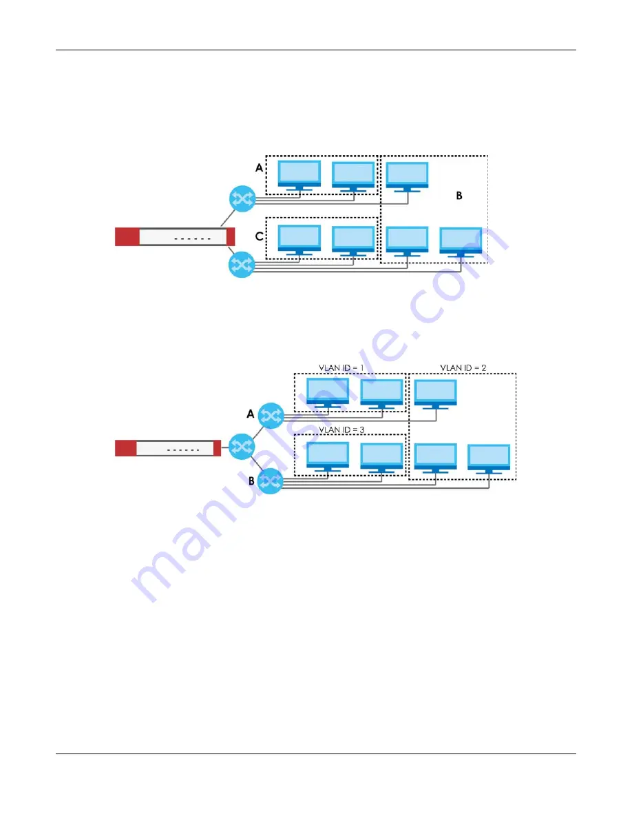
Figure 188
Example: Before VLAN
In this example, there are two physical networks and three departments
A
,
B
, and
C
. The physical
networks are connected to hubs, and the hubs are connected to the router.
Alternatively, you can divide the physical networks into three VLANs.
Figure 189
Example: After VLAN
Each VLAN is a separate network with separate IP addresses, subnet masks, and gateways. Each VLAN
also has a unique identification number (ID). The ID is a 12-bit value that is stored in the MAC header. The
VLANs are connected to switches, and the switches are connected to the router. (If one switch has
enough connections for the entire network, the network does not need switches
A
and
B
.)
• Traffic inside each VLAN is layer-2 communication (data link layer, MAC addresses). It is handled by
the switches. As a result, the new switch is required to handle traffic inside VLAN 2. Traffic is only
broadcast inside each VLAN, not each physical network.
• Traffic between VLANs (or between a VLAN and another type of network) is layer-3 communication
(network layer, IP addresses). It is handled by the router.
This approach provides a few advantages.
• Increased performance - In VLAN 2, the extra switch should route traffic inside the sales department
faster than the router does. In addition, broadcasts are limited to smaller, more logical groups of users.
• Higher security - If each computer has a separate physical connection to the switch, then broadcast
traffic in each VLAN is never sent to computers in another VLAN.


