Chapter 18 Multicast
GS-2024 User’s Guide
135
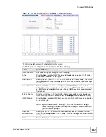
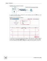
Figure 68
Advanced Application > Multicast > Multicast Setting > MVR: Group Configuration
The following table describes the labels in this screen.
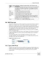
18.8.1 MVR Configuration Example
The following figure shows a network example where ports 1, 2 and 3 on the Switch belong to
VLAN 1. In addition, port 7 belongs to the multicast group with VID 200 to receive multicast
traffic (the
News
and
Movie
channels) from the remote streaming media server,
S
. Computers
A, B and C in VLAN 1 are able to receive the traffic.
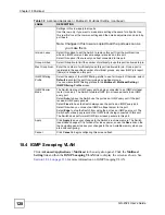
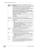
Table 43
Advanced Application > Multicast > Multicast Setting > MVR: Group Configuration
LABEL
DESCRIPTION
Multicast
VLAN ID
Select a multicast VLAN ID (that you configured in the
MVR
screen) from the drop-
down list box.
Name
Enter a descriptive name for identification purposes.
Start Address
Enter the starting IP multicast address of the multicast group in dotted decimal
notation.
Refer to
for more information on IP multicast addresses.
End Address
Enter the ending IP multicast address of the multicast group in dotted decimal notation.
Enter the same IP address as the
Start Address
field if you want to configure only one
IP address for a multicast group.
Refer to
for more information on IP multicast addresses.
Add
Click
Add
to save your changes to the Switch’s run-time memory. The Switch loses
these changes if it is turned off or loses power, so use the
Save
link on the top
navigation panel to save your changes to the non-volatile memory when you are done
configuring.
Cancel
Click
Cancel
to begin configuring this screen afresh.
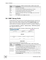
MVLAN
This field displays the multicast VLAN ID.
Name
This field displays the descriptive name for this setting.
Start Address
This field displays the starting IP address of the multicast group.
End Address
This field displays the ending IP address of the multicast group.
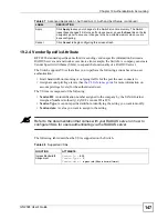
Delete Select
Delete All
or
Delete Group
and click
Delete
to remove the selected entry(ies)
from the table.
Cancel Select
Cancel
to clear the checkbox(es) in the table.
Summary of Contents for Dimension GS-2024
Page 2: ......
Page 7: ...Safety Warnings GS 2024 User s Guide 7 This product is recyclable Dispose of it properly ...
Page 8: ...Safety Warnings GS 2024 User s Guide 8 ...
Page 26: ...List of Tables GS 2024 User s Guide 26 ...
Page 28: ...28 ...
Page 36: ...Chapter 2 Hardware Installation and Connection GS 2024 User s Guide 36 ...
Page 44: ...44 ...
Page 62: ...Chapter 6 System Status and Port Statistics GS 2024 User s Guide 62 ...
Page 70: ...Chapter 7 Basic Setting GS 2024 User s Guide 70 Figure 27 Basic Setting IP Setup ...
Page 74: ...Chapter 7 Basic Setting GS 2024 User s Guide 74 ...
Page 76: ...76 ...
Page 88: ...Chapter 8 VLAN GS 2024 User s Guide 88 ...
Page 110: ...Chapter 13 Mirroring GS 2024 User s Guide 110 ...
Page 120: ...Chapter 15 Port Authentication GS 2024 User s Guide 120 ...
Page 138: ...Chapter 18 Multicast GS 2024 User s Guide 138 ...
Page 152: ...Chapter 19 Authentication Accounting GS 2024 User s Guide 152 ...
Page 157: ...157 PART IV IP Application Static Route 159 Differentiated Services 163 DHCP 167 ...
Page 158: ...158 ...
Page 162: ...Chapter 21 Static Route GS 2024 User s Guide 162 ...
Page 166: ...Chapter 22 Differentiated Services GS 2024 User s Guide 166 ...
Page 174: ...174 ...
Page 198: ...Chapter 25 Access Control GS 2024 User s Guide 198 ...
Page 200: ...Chapter 26 Diagnostic GS 2024 User s Guide 200 ...
Page 204: ...Chapter 27 Syslog GS 2024 User s Guide 204 ...
Page 218: ...218 ...
Page 222: ...Chapter 32 Troubleshooting GS 2024 User s Guide 222 ...
Page 230: ...Chapter 33 Product Specifications GS 2024 User s Guide 230 ...
Page 232: ...232 ...
Page 240: ...Appendix A Pop up Windows JavaScripts and Java Permissions GS 2024 User s Guide 240 ...
Page 252: ...Appendix C Legal Information GS 2024 User s Guide 252 ...
Page 258: ...Appendix D Customer Support GS 2024 User s Guide 258 ...
Page 266: ...Index GS 2024 User s Guide 266 ...

