Chapter 2 Hardware Description and Connection
ES1100 Series User’s Guide
16
2.3 Hardware Installation
See t he follow ing t able for a com par ison of t he har dwar e inst allat ion m et hods of each ES1100
m odel:
Table 5 ES1100 Series I nst allat ion Com parison Table
Not e: Ask an aut hor ized t echnician t o at t ach t he Sw it ch t o t he rack / wall.
For ES1100- 8P/ 16/ 16P/ 24E, you can place t he Sw it ch dir ect ly on t op of your desk or have it rack-
m ount ed. For ES1100- 24, t he size is suit able for rack- m ount ing and you can r efer t o
Sect ion 2.3.2
on page 17
for inst ruct ion. Take not e of t he follow ing:
•
The Swit ch should have a m inim um 25 m m space ar ound it for vent ilat ion.
•
The Swit ch should be placed in a desk t hat has a level sur face and t hat is able t o suppor t t he
w eight of t he Swit ch.
To st ar t using it , sim ply connect t he pow er cables and t ur n on t he Swit ch.
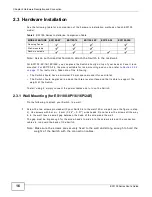
2.3.1 Wall Mounting (for ES1100-8P/16/16P/24E)
Do t he follow ing t o at t ach your Sw it ch t o a wall.
1
Scr ew t he t w o scr ews pr ovided w it h your Swit ch int o t he wall 150 m m apart ( see t he figure in st ep
2) . Use screws w it h 6 m m ~ 8 m m ( 0.24" ~ 0.31" ) w ide heads. Do not scr ew t he scr ew s all t he way
in t o t he wall; leave a sm all gap bet w een t he head of t he scr ew and t he wall.
The gap m ust be big enough for t he scr ew heads t o slide int o t he scr ew slot s and t he connect ion
cables t o r un dow n t he back of t he Swit ch.
Not e: Make sur e t he scr ew s ar e secur ely fixed t o t he wall and st r ong enough t o hold t he
w eight of t he Sw it ch w it h t he connect ion cables.
MODEL FEATURE
ES1100-8P
ES1100-16
ES1100-16P
ES1100-24
ES1100-24E
Desk t op Dev ice
Wall- m ount able
Rack- m ount able


