background image

ES1100 Series User’s Guide

20

C

H A P T E R

      3

Troubleshooting

This sect ion descr ibes com m on pr oblem s you m ay encount er  w it h t he Swit ch and possible 
solut ions. 

Tr oubleshoot  t he Sw it ch using t he LEDs t o det ect  pr oblem s.

The PWR LED on t he fr ont  panel does not  light  up.  

Check t he connect ions fr om  your  Sw it ch t o t he pow er  sour ce.  Make sur e you ar e using t he 

supplied pow er  cor d and t hat  you ar e using an appr opr iat e pow er  sour ce. Refer  t o t he pr oduct  
specificat ions.

Make sur e t he pow er  sour ce is t ur ned on and t hat  t he Sw it ch is r eceiving sufficient  pow er.

I f t hese st eps fail t o cor r ect  t he pr oblem , cont act your  local dist r ibut or  for  assist ance. 

The LI N K/ ACT LED does not  light  up w hen a dev ice is connect ed. 

Ver ify t hat  t he at t ached device( s)  is t ur ned on and pr oper ly connect ed t o your  Swit ch. 

Make sur e t he net w or k adapt er s ar e w or king on t he at t ached devices. 

Verify t hat  pr oper net w ork cable t ype is used and it s lengt h does not  exceed 100 m et ers. For 

m ore infor m at ion on net w or k cable t y pes, see 

Sect ion 3.1 on page 21

.

The PWR LED is off and/ or  pow er  is not  being supplied t o m y PoE- enabled dev ice. ( For  
ES1100- 8P and ES1100- 16P)

Check t o see t hat  t he pow er  cor d is secur ely connect ed t o t he ES1100- 8P/ 16P and an 

appropr iat e pow er  sour ce. Make sur e t he pow er  sour ce is on and funct ioning pr oper ly. 

Check t hat  t he Et her net  cables ar e connect ed pr oper ly and t hat  you ar e using t he cor r ect  t ype of 

Et hernet  cable. Cont act  your local dist r ibut or if t he problem  persist s.

Summary of Contents for ES1100-16

Page 1: ...www zyxel com www zyxel com ES1100 Series 8 16 24 Port Unmanaged Fast Ethernet Switch Copyright 2011 ZyXEL Communications Corporation Version 1 00 Edition 2 4 2011 ...

Page 2: ......

Page 3: ...om this link Read the Tech Doc Overview to find out how to efficiently use the User Guide Quick Start Guide and Command Line Interface Reference Guide in order to better understand how to use your product Knowledge Base If you have a specific question about your product the answer may be here This is a collection of answers to previously asked questions about ZyXEL products Forum This contains dis...

Page 4: ... com web contact_us php for contact information Please have the following information ready when you contact an office Product model and serial number Warranty Information Date that you received your device Brief description of the problem and the steps youtook to solve it ...

Page 5: ...en names field labels and fie ld choices are all in bold font A key stroke is denoted by square brackets and upp ercase text for example ENTER means the enter or return key on your keyboard Enter means for you to type one or more characte rs and then press the ENTER key Select or choose means for you to use one of the predefined choices Units of measurement may denote the metric va lue or the scie...

Page 6: ...mble over them Always disconnect all cables from thisdevice before servicing or disassembling Use ONLY an appropriate power adaptor or cord foryour device Connect it to the right supply voltage for example 110V AC in North America or 230V AC in Europe Use ONLY power wires of the appropriate wire gaugefor your device Connect it to a power supply of the correct voltage Do NOT allow anything to rest ...

Page 7: ...PoE 12 Chapter 2 Hardware Description and Connection 13 2 1 Rear Panel 13 2 1 1 Rear Panel Power Connection 13 2 2 Front Panel 14 2 2 1 RJ 45 Auto negotiating Ports 14 2 2 2 Front Panel Connections 14 2 2 3 Front Panel LEDs 15 2 3 Hardware Installation 16 2 3 1 Wall Mounting for ES1100 8P 16 16P 24E 16 2 3 2 Rack Mounting 17 2 3 3 Mounting the Switch on a Rack 19 Chapter 3 Troubleshooting 20 3 1 I...

Page 8: ...Table of Contents ES1100 Series User s Guide 8 ...

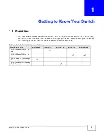
Page 9: ...h can be used to build high performance switched workgroup networks The following table lists features that are specific to individual models Table 1 ES1100 Series Comparison Table MODEL FEATURE ES1100 8P ES1100 16 ES1100 16P ES1100 24 ES1100 24E 16x10 100Base TX Ethernet Ports 24x10 100Base TX Ethernet Ports 8x10 100Base TX including 4 FE PoE ports 16x10 100Base TX including 8 FE PoE ports ...

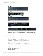
Page 10: ...standar ds ES1000 8P and ES1100 16P support IEEE 802 3af PoEstandard Auto negotiating 10 100 Mbps Ethernet RJ 45ports ES1000 8P and ES1100 16P include FE PoE ports Auto sensing crossover for all 10 100 Mbps Etherne t RJ 45 ports Supports N Way protocol for speed 10 100 Mbps an d duplex mode Half Full auto detection Supports store and forward switching Supports automatic address learning Full wire ...

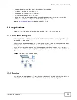
Page 11: ... 3 1 Standalone Workgroup In this application the Switch is an ideal solution for small networks where rapid growth can be expected in the near future The Switch can be used standalone for a group of heavy traffic users You can connect computers directly to the Switch s port or connect other switches to the Switch In this example all computers can share high speed applications on the server To exp...

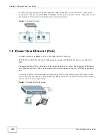
Page 12: ...is available for ES1100 8P and ES1100 16P only ES1000 8P and ES1100 16P has FE PoE ports and supports IEEE 802 3af Power over Ethernet PoE A powered device PD is a device such as an access point or a switch that supports PoE Power over Ethernet so that it can receive power from another device through a 10 100Mbps Ethernet port In the figure below the IP camera and IP phone get their power directly...

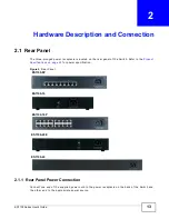
Page 13: ... rear panel of the Switch Refer to the Product Specifications on page 23 for power specification Figure 5 Rear Panel 2 1 1 Rear Panel Power Connection Connect one end of the supplied power cord to the power receptacle on the back of the Switch and the other end to the appropriate power source ES1100 8P ES1100 16 ES1100 16P ES1100 24E ES1100 24 ...

Page 14: ...to the optimum Ethernet speed 10 100 Mpbs and duplex mode full duplex or half duplex of the connected device An auto crossover auto MDI MDI X port automatically works with a straight through or crossover Ethernet cable 2 2 2 Front Panel Connections You can use unshielded twisted pair UTP or shielded twisted pair STP Ethernet cables for RJ 45 ports The following table describes the types of network...

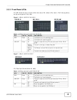
Page 15: ... ACT Green On The port is connected to an Ethernet network at 10M or 100M speed Blinking Normal The port is receiving or transmitting data Blinking Slow The Ethernet network link is down due to loop detection Off The port is not connected to an Ethernet network Table 4 LED Descriptions for ES1100 8P 16P LED COLOR STATUS DESCRIPTION PWR Green On The Switch is on and receiving power Off The Switch i...

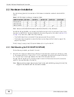
Page 16: ... ha s a level surface and that is able to support the weight of the Switch To start using it simply connect the power cables and turn on the Switch 2 3 1 Wall Mounting for ES1100 8P 16 16P 24E Do the following to attach your Switch to a wall 1 Screw the two screws provided with your Switch into the wall 150 mm apart see the figure in step 2 Use screws with 6 mm 8 mm 0 24 0 31 wide heads Do not scr...

Page 17: ...iring closet with other equipment Follow the steps below to mount your Switch on a standard EIA rack using a rack mounting kit Rack mounted Installation Requirements Two mounting brackets Eight M3 flat head screws and a 2 Philips screwdr iver Four M5 flat head screws and a 2 Philips screwdri ver Failure to use the proper screws may damage the unit Precautions Make sure the rack will safely support...

Page 18: ...he screw holes on the side of the Switch Figure 8 Attaching the Mounting Brackets ES1100 8P 16 16P 24E Figure 9 Attaching the Mounting Brackets ES1100 24 2 Using a 2 Philips screwdriver install the M3 flat head screws through the mounting bracket holes into the Switch 3 Repeat steps 1 and 2 to install the second mounting bracket on the other side of the Switch 4 You may now mount the Switch on a r...

Page 19: ... lining up the two screw holes on the bracket with the screw holes on the side of the rack Figure 10 Mounting the Switch on a Rack ES1100 8P 16 16P 24E Figure 11 Mounting the Switch on a Rack ES1100 24 2 Using a 2 Philips screwdriver install the M5 flat head screws through the mounting bracket holes into the rack 3 Repeat steps 1 and 2 to attach the second mounting bracket on the other side of the...

Page 20: ...assistance The LI NK ACT LED does not light up when a device is connected Verify that the attached device s is turnedon and properly connected to your Switch Make sure the network adapters are working on theattached devices Verify that proper network cable type is used andits length does not exceed 100 meters For more information on network cable types see Section 3 1 on page 21 The PWR LED is off...

Page 21: ...lems that affect your network performance Refer to Section 2 2 2 on page 14 for more information on network cable types Cabling Length If you use longer cables than are needed transmission quality may be affected The network cables should not be longer than the limit of 100 meters Too many hubs between the computers in the network Too many hubs or repeaters between the connected computers in the n...

Page 22: ...Chapter 3 Troubleshooting ES1100 Series User s Guide 22 ...

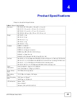
Page 23: ...802 1p Class of Service IEEE 802 3af PoE standard ES1000 8P and ES1100 16P Interface ES1100 8P 8 x 10 100 Mbps auto MDI MDI X RJ 45 switching port including 4 FE PoE ports ES1100 16P 16 x 10 100 Mbps auto MDI MDI X RJ 45 switch port including 8 FE PoE ports ES1100 16 16 x 10 100 Mbps auto MDI MDI X RJ 45 switching ports ES1100 24 24E 24 x 10 100 Mbps auto MDI MDI X RJ 45 switching ports Cable Conn...

Page 24: ...048 bytes for ES1100 16 24 24E Operating Temperature 0 50 oC Storage Temperature 40 70 o C Operating Humidity 10 95 non condensing PoE Power Budget ES1100 8P 64W ES1100 16P 130W Power Supply Power rating 100 240 V 50 60 Hz 0 5 A Max Power consumption ES1100 8P 74 9W max ES1100 16 2 65W max ES1100 16P 161 6 W max ES1100 24 4 05W max ES1100 24E 4 05W max Safety EN 60950 1 EMC FCC Part15 Class A CE E...

Page 25: ...s Federal Communications Commission FCC Interference Statement This device complies with Part 15 of FCC rules Operation is subject to the following two conditions This device may not cause harmful interference This device must accept any interference re ceived including interference that may cause undesired operations FCC Warning This device has been tested and found to comply with the limits for ...

Page 26: ...e product or components to proper operating condition Any replacement will consist of a new or re manufactured functionally equivalent product of equal or higher value and will be solely at the discretion of ZyXEL This warranty shall not apply if the product has been modified misused tampered with damaged by an act of God or subjected to abnormal working conditions Note Repair or replacement as pr...

Page 27: ...s 21 FCC interference statement 25 Front Panel 14 Front Panel Connections 14 I installation precautions 17 L LED Descriptions LK ACT 15 PWR 15 M mounting brackets 18 N network cable crossover 14 straight through 14 Network Cable Types 14 Non standard network cables 21 P product registration 26 Product specification 23 R rack mounting 17 Rear Panel 13 Rear Panel Power Connection 13 registration pro...

Page 28: ...Index ES1100 Series User s Guide 28 Standalone Workgroup 11 syntax conventions 5 T Troubleshooting Improper Network Cabling and Topology 21 W wall mounting 16 warranty 26 note 26 ...

Page 29: ...Index ES1100 Series User s Guide 29 ...

Page 30: ...Index ES1100 Series User s Guide 30 ...

Reviews: