background image

GS-105/GS-108 Gigabit Switch 

Desktop Installation                            

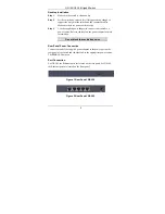
Step 1. 

Make sure the switch is clean and dry. 

Step 2. 

Set the switch on a smooth, level flat space strong enough to 
support the weight of the switch and the connected cables. 
Make sure there is a power outlet nearby.  

Step 3. 

Use the supplied power adapter to connect your switch to a 
power source. Refer to the label on the power adapter for more 
information. 

 Do not block the ventilation holes.  

Rear Panel Power Connection 

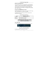
Connect one end of the supplied power adaptor to the power port on the 
rear panel of the switch and the other end to the appropriate power source. 
The 

PWR 

LED turns on.  

Port Connection 

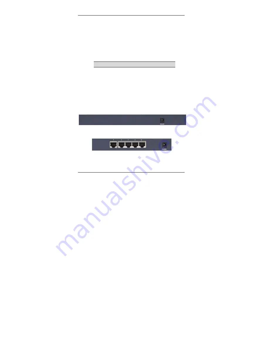
For GS-105, the Ethernet ports are located on the rear panel. For GS-108, 
the Ethernet ports are located on the front panel.   

Figure 1 Rear Panel: GS-108 


Figure 2 Rear Panel: GS-105 


Summary of Contents for GS-105

Page 1: ...GS 105 GS 108 Gigabit Switch User s Guide Version 1 0 April 2003 ...

Page 2: ...nable protection against harmful interference in a commercial environment This equipment generates uses and can radiate radio frequency energy and if not installed and used in accordance with the instruction manual may cause harmful interference to radio communications Operation of this equipment in a residential area is likely to cause harmful interference in which case the user will be required ...

Page 3: ...t of God or subjected to abnormal working conditions Note Repair or replacement as provided under this warranty is the exclusive remedy of the purchaser This warranty is in lieu of all other warranties express or implied including any implied warranty of merchantability or fitness for a particular use or purpose ZyXEL shall in no event be held liable for indirect or consequential damages of any ki...

Page 4: ... latency for high speed networking The switch is designed for SOHO Small Office Home Office businesses Standalone Workgroup Application The switch can be used as a standalone switch to which computers servers and print server are directly connected to form a small workgroup Standalone Workgroup Example Hardware Installation and Connection The switch is suitable for an office environment where it c...

Page 5: ...t your switch to a power source Refer to the label on the power adapter for more information Do not block the ventilation holes Rear Panel Power Connection Connect one end of the supplied power adaptor to the power port on the rear panel of the switch and the other end to the appropriate power source The PWR LED turns on Port Connection For GS 105 the Ethernet ports are located on the rear panel F...

Page 6: ...et Ports Each Ethernet port allows you to connect to a computer or to a hub using either a straight through or a crossover Ethernet cable The following table describes the types of network cable used for the different connection speeds Table 1 Ethernet Cable Type SPEED NETWORK CABLE TYPE 10 Base T 100Ω 2 pair UTP STP Category 3 4 or 5 100 Base TX 100Ω 2 pair UTP STP Category 5 1000 Base T 100Ω 4 p...

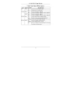
Page 7: ...e is attached Orange On The port is operating at 100Mbps Off The port is operating at 10Mbps or no device is attached LNK ACT Green On The port is connected to an Ethernet network Off The port is not connected to an Ethernet network Blinking The port is receiving or transmitting data Orange On The port is operating in full duplex mode Blinking Packet collision occurred on this port FDX COL Off The...

Reviews: