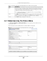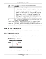
Chapter 13 Spanning Tree Protocol
XMG1930 Series User’s Guide
149
blocking state to forwarding state so as to eliminate transient loops.
Multiple STP
Multiple Spanning Tree Protocol (IEEE 802.1s) is backward compatible with STP/RSTP and addresses the
limitations of existing spanning tree protocols (STP and RSTP) in networks to include the following
features:
• One Common and Internal Spanning Tree (CIST) that represents the entire network’s connectivity.
• Grouping of multiple bridges (or switching devices) into regions that appear as one single bridge on
the network.
• A VLAN can be mapped to a specific Multiple Spanning Tree Instance (MSTI). MSTI allows multiple
VLANs to use the same spanning tree.
• Load-balancing is possible as traffic from different VLANs can use distinct paths in a region.
13.2 Spanning Tree Protocol Status
The Spanning Tree Protocol status screen changes depending on what standard you choose to
implement on your network. Click
Advanced Application
>
Spanning Tree Protocol
to see the screen as
shown.
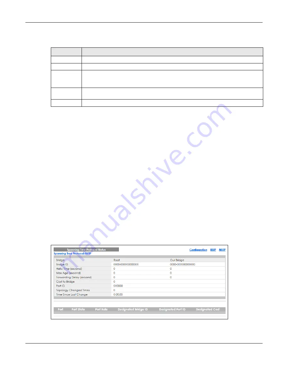
Figure 106
Advanced Application > Spanning Tree Protocol
This screen differs depending on which STP mode (RSTP or MSTP) you configure on the Switch. This screen
is described in detail in the section that follows the configuration section for each STP mode. Click
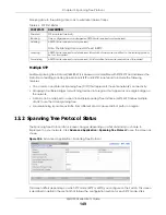
Table 65 STP Port States
PORT STATE
DESCRIPTION
Disabled
STP is disabled (default).
Blocking
Only configuration and management BPDUs are received and processed.
Listening
All BPDUs are received and processed.
Note: The listening state does NOT exist in RSTP.
Learning
All BPDUs are received and processed. Information frames are submitted to the learning process
but not forwarded.
Forwarding
All BPDUs are received and processed. All information frames are received and forwarded.


