background image

MGS3750-28F User’s Guide

18

C

H A P T E R

      5

Basic Settings

5.1  System Info

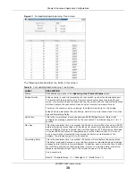
View basic system information. The IP address and system name can also be set here.

Figure 11   

System Information Screen

The following table describes the labels in this screen. 

Table 4   

System Information Screen 

LABEL

DESCRIPTION

Product 
description

This field displays the descriptive name of the Switch for identification purposes. 

bootrom 
version

This field displays the version number of the Switch’s bootrom.

Software 
Version

This field displays the version number of the Switch's current software.

MAC Address 

This field displays the MAC addresses of the Switch.

IP address

This field displays the current IP address of the Switch.

Subnet mask

This field displays the current subnet mask.

Default 
Gateway

This is the IP address of the default gateway, if applicable.

System 
startup time

This field displays how long the Switch has been running since it last started up.

System 
Application

This field displays whether the Switch runs on default or secondary software application.

Switch 
temperature

The Switch has temperature sensors that are capable of detecting and reporting if the 
temperature rises above the threshold. 

System Name

This field displays the name used to identify the Switch on any network.

Summary of Contents for MGS3750-28F

Page 1: ... www zyxel com MGS3750 28F MetroGigabit Switch Version 1 02 Edition 2 11 2016 Copyright 2016 ZyXEL Communications Corporation User s Guide Default Login Details IP Address http 192 168 1 1 User Name admin Password 1234 ...

Page 2: ...raphics in this book may differ slightly from your product due to differences in your product firmware or your computer operating system Every effort has been made to ensure that the information in this manual is accurate Related Documentation CLI Reference Guide The CLI Reference Guide explains how to use the Command Line Interface CLI and CLI commands to configure the Switch More Information Go ...

Page 3: ...28F User s Guide 3 Contents Overview Hardware Installation and Connection 7 Hardware Overview 10 Logging into the Web Interface 15 Overall Web Page Layout 16 Basic Settings 18 Advanced Application Configurations 22 Management 61 ...

Page 4: ...e Mounting Brackets to the Switch 8 1 3 3 Mounting the Switch on a Rack 8 Chapter 2 Hardware Overview 10 2 1 Front Panel 10 2 1 1 Console Port 10 2 1 2 Transceiver Slots 11 2 1 3 Power Connector 13 2 2 LEDs 14 Chapter 3 Logging into the Web Interface 15 3 1 Launch Browser 15 Chapter 4 Overall Web Page Layout 16 4 1 Port Status 16 Chapter 5 Basic Settings 18 5 1 System Info 18 5 2 General Applicati...

Page 5: ...g 40 6 10 Link Aggregation 41 6 10 1 Link Aggregation Setting 42 6 10 2 Link Aggregation Control Protocol 44 6 10 3 Group ID 44 6 10 4 Port 45 6 11 Port Security 45 6 12 Classifier 47 6 13 Policy Rule 50 6 14 Queuing Method 52 6 15 Multicast 53 6 15 1 Multicast Setting 54 6 15 2 IGMP Snooping Deny VLAN 55 6 15 3 IGMP Filtering Profile 56 6 16 CPU Queue Control 57 6 17 DoS Attack Control 58 Chapter...

Page 6: ...Table of Contents MGS3750 28F User s Guide 6 Appendix A Customer Support 71 Appendix B Legal Information 77 ...

Page 7: ...he Switch is clean and dry 2 Set the Switch on a smooth level surface strong enough to support the weight of the Switch and the connected cables Make sure there is a power outlet nearby 3 Make sure there is enough clearance around the Switch to allow air circulation and the attachment of cables and the power cord 1 3 Mounting the Switch on a Rack The Switch can be mounted on an EIA standard size 1...

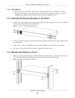
Page 8: ...ing up the four screw holes on the bracket with the screw holes on the side of the Switch Figure 1 Attaching the Mounting Brackets 2 Using a 2 Philips screwdriver install the M3 flat head screws through the mounting bracket holes into the Switch 3 Repeat steps 1 and 2 to install the second mounting bracket on the other side of the Switch 4 You may now mount the Switch on a rack Proceed to the next...

Page 9: ...nnection MGS3750 28F User s Guide 9 2 Using a 2 Philips screwdriver install the M5 flat head screws through the mounting bracket holes into the rack 3 Repeat steps 1 and 2 to attach the second mounting bracket on the other side of the rack ...

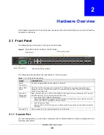
Page 10: ...L DESCRIPTION Power Connection Connect an appropriate power supply to this port SFP or SFP Slots Use SFP or SFP transceivers in these slots for fiber optic or copper connections to a computer a hub a switch or a router You can also insert a SFP Direct Attach Copper DAC in the SFP Slot Four Dual Personality Interfaces Each interface has one 10 100 1000 BASE T RJ 45 port and one transceiver slot You...

Page 11: ...s and switches hubs 2 1 2 Transceiver Slots These are slots for mini GBIC Gigabit Interface Converter transceivers or 100 Mbps Small Form factor Pluggable SFP transceivers A transceiver is a single unit that houses a transmitter and a receiver The Switch does not come with transceivers You must use transceivers that comply with the SFP Transceiver MultiSource Agreement MSA See the SFF committee s ...

Page 12: ...e transceiver Figure 4 Transceiver Installation Example Figure 5 Connecting the Fiber Optic Cables 2 1 2 2 Transceiver Removal Use the following steps to remove a mini GBIC transceiver SFP module 1 Remove the fiber optic cables from the transceiver 2 Open the transceiver s latch latch styles vary 3 Pull the transceiver out of the slot Figure 6 Removing the Fiber Optic Cables Figure 7 Opening the T...

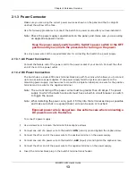
Page 13: ...ne power supply fails the system can operate on the remaining power supply Use two wires to connect to a single terminal pair one wire for the positive terminal and one wire for the negative terminal Note The current rating of the power wires must be greater than 20 Amps The power supply to which the Switch connects must have a built in circuit breaker or switch to toggle the power Note When insta...

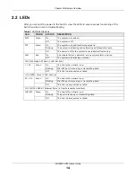
Page 14: ... malfunctioning ALM Red On A hardware failure is detected or an external alarm is active Off The system is functioning normally 100 1000 Mbps SFP Slots 1 LED Per Port 1 24 Green On The link to the network is up Blinking Mini SFP port is receiving or transmitting data Off This link is disconnected or failed 1 10G SFP Slots 1 LED Per Port 25 28 Green On The link to the network is up Blinking Mini SF...

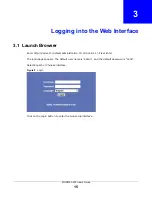
Page 15: ...ch Browser Enter http device IP default administration IP 192 168 1 1 Press Enter The login page appears The default user name is admin and the default password is 1234 Select English or Chinese interface Figure 9 Login Click on the Login button to enter the web setup interface ...

Page 16: ...RIPTION Port This identifies the Ethernet port Click a port number to display the Port Details screen Name This is the name you assigned to this port in the Port Setup screen Link This field displays the speed either 10 for 10Mbps 100 for 100Mbps 1000 for 1000bps or 10000 for 1Gbps and the duplex F for full duplex or H for half It also shows the cable type Copper or Fiber for the combo ports Set S...

Page 17: ... number of transmitted frames on this port RxPkts This field shows the number of received frames on this port Errors This field shows the number of received errors on this port Tx KB s This field shows the number of kilobytes per second transmitted on this port Rx KB s This field shows the number of kilobytes per second received on this port Up Time This field shows the total amount of time in hou...

Page 18: ... of the Switch s current software MAC Address This field displays the MAC addresses of the Switch IP address This field displays the current IP address of the Switch Subnet mask This field displays the current subnet mask Default Gateway This is the IP address of the default gateway if applicable System startup time This field displays how long the Switch has been running since it last started up ...

Page 19: ...t this device is System object ID An OID Object ID that begins with 1 3 6 1 4 1 890 1 5 8 81 is defined in private MIBs Otherwise it is a standard MIB OID System port quantity This field displays how many ports the Switch has System startup time This field displays how long the Switch has been running since it last started up System Name Choose a descriptive name for identification purposes This n...

Page 20: ...creen LABEL DESCRIPTION by MANUAL Select by MANUAL to configure IP address subnet mask and default gateway manually IP Address This field displays IP address of the Switch in the IP domain Default Gateway This is the IP address of the default gateway if applicable Subnet mask This field displays the current subnet mask System MAC address This field displays the MAC addresses of the Switch Refresh ...

Page 21: ... field helps you set port speed The speed is set to auto by default Mode Select the speed and the duplex mode of the Ethernet connection on this port Selecting auto auto negotiation allows one port to negotiate with a peer port automatically to obtain the connection speed and duplex mode that both ends support You can also select other options such as Master and Slaver Actual Speed This field disp...

Page 22: ... in the list below Leave this field blank and click Search to display all VLANs configured on the Switch The Number of VLAN This is the number of VLANs configured on the Switch The Number of Search Results This is the number of VLANs that match the searching criteria and display in the list below This field displays only when you use the Search button to look for certain VLANs Index This is the VL...

Page 23: ...ed as a private VLAN primary isolated or community Port Number This column displays the ports that are participating in a VLAN A tagged port is marked as T an untagged port is marked as U and ports not participating in a VLAN are marked as Table 8 VLAN Status Screen continued LABEL DESCRIPTION Table 9 VLAN Port Settings Screen LABEL DESCRIPTION VLAN Status Return to the VLAN status page Global GVR...

Page 24: ...ort All untagged frames will be dropped Select Untag Only to accept only untagged frames on this port All tagged frames will be dropped Port Mode Edit the port mode there are three port modes Select Hybrid mode and port can be tagged or untagged within a VLAN it can also be a member of multiple VLANs Select Trunk mode and port must be tagged within a VLAN it can also be a member of multiple VLANs ...

Page 25: ... Number This column displays the ports that are participating in a VLAN A tagged port is marked as T an untagged port is marked as U and ports not participating in a VLAN are marked as VLAN Group ID Enter the VLAN ID for this static entry the valid range is between 1 and 4094 Name Enter a descriptive name for the VLAN group for identification purposes This name consists of up to 64 printable chara...

Page 26: ...ally entered in the MAB address table and not age out When setting up the MAC Address rules to a port may reduce the need for broadcasting Port No Blackhole Mac Enter a port that the MAC address was entered in the previous field and it will be forwarded automatically Add Click Add to save your rule to the Switch s run time memory The Switch loses this rule if it is turned off or loses power Cancel...

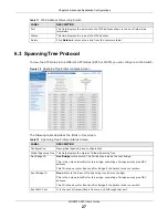
Page 27: ... Table 12 Spanning Tree Protocol Status Screen LABEL DESCRIPTION Configuration Open global spanning tree configurations Global Spanning Tree This field displays the status of Global Spanning Tree Our Bridge ID Our Bridge is this switch This Switch may also be the root bridge This is the unique identifier for this bridge consisting of bridge priority plus MAC address This ID is the same for Root an...

Page 28: ...ng to the speed of the bridge The slower the media the higher the cost Priority Configure the priority for each port here Priority decides which port should be disabled when more than one port forms a loop in a switch Ports with a higher priority numeric value are disabled first The allowed range is between 0 and 255 and the default value is 128 Role This field displays the role of the port in STP...

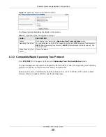
Page 29: ...cluding global port priority port spanning tree status and path cost Bridge priority can be modified by default bridge priority is set to 32768 STP protocol packet interval Maximum packet lifetime and forwarding delay Table 13 Spanning Tree Configuration Screen LABEL DESCRIPTION Status Click Status to go back to the Spanning Tree Protocol Status screen Spanning Tree Mode You can activate one of th...

Page 30: ...n seconds between BPDU Bridge Protocol Data Units configuration message generations by the root switch The allowed range is 1 to 10 seconds Max Age This is the maximum time in seconds the Switch can wait without receiving a BPDU before attempting to reconfigure All Switch ports except for designated ports should receive BPDUs at regular intervals Any port that ages out STP information provided in ...

Page 31: ...rt forms a loop in a switch Ports with a higher priority numeric value are disabled first The allowed range is between 0 and 255 and the default value is 128 Path Cost Path cost is the cost of transmitting a frame on to a LAN through that port It is recommended to assign this value according to the speed of the bridge The slower the media the higher the cost Table 14 Compatible Rapid Spanning Tree...

Page 32: ...to begin configuring this screen afresh Instance Instances can be added or removed from the table For example if instance 1 is added with instance priority 20480 default is 32768 then it mirrors VLAN 10 20 The port status for MSTP spanning tree can be configured configuration is identical to the RSTP port Instance Enter the number you want to use to identify this MST instance on the Switch The Swi...

Page 33: ...LABEL DESCRIPTION Global ERPS Status Enable disable ERPS function for the entire zone Instance Instance range is from 0 15 it works in a way similar to domains in ERRP Search Click Search to find instances Meg Level Used with CFM and is consistent with CFM level CFM is mainly used for faults other than linkdown such as one way connections ERPS will work normally if CFM is disabled but will not be ...

Page 34: ...then owner and neighbor ports will be in the discarding mode while other ports will be in the forwarding mode Add Click Add to insert the entry in the summary table below and save your changes to the Switch s run time memory The Switch loses these changes if it is turned off or loses power Remove Click Remove to clear the configurations Table 16 ERPS Screen LABEL DESCRIPTION Table 17 Instance Scre...

Page 35: ...rward Type a figure to define a time that the transit node will stay in the Pre forwarding state with the port recovered blocked if the temporary loop occurs Pre Up Type a figure to configure recovery timer value Apply Click Apply to save your changes to the Switch s run time memory The Switch loses these changes if it is turned off or loses power Cancel Click Cancel to begin configuring this scre...

Page 36: ... you selected Topo Collect This field displays whether Topo Collect is enabled or not Ring List This field display the ring ID 0 means master ring 1 means rub ring Delete Click Delete to remove the selected entry from the summary table Table 20 EAPS Screen LABEL DESCRIPTION Active Select this option to enable the ring Ring ID Select the ring ID 0 means master ring 1 means sub ring Query Solicit Cl...

Page 37: ...ear Click Clear to delete the configurations of the above fields Table 21 EAPS Screen LABEL DESCRIPTION Ring ID This field displays the ring ID 0 means master ring 1 means sub ring Active This field displays whether the Ring ID is active or not Role This field displays whetehr the Bridge Role is master or transit Level This field displays the ring level Stm This field displays the statement Query ...

Page 38: ...that STP can run properly across the service provider s network and spanning trees can be set up based on bridge information from all local and remote networks VTP Select this option to have the Switch tunnel VTP VLAN Trunking Protocol packets so that all customer switches can use consistent VLAN configuration through the service provider s network Point to Point The Switch supports PAgP Port Aggr...

Page 39: ...t and or Unicast packets is reached per second the subsequent packets are discarded Enable this feature to reduce broadcast multicast and or Unicast packets in your network You can specify limits for each packet type on each port Figure 31 Broadcast Storm Control Screen Table 23 Bandwidth Control Screen LABEL DESCRIPTION Port This field displays the port number Ingress Rate Specify the maximum ban...

Page 40: ...f unknown unicast packets that the port can receive each second The unit is packets per second and its actual value must be a multiple of 64 Table 25 Mirroring Screen LABEL DESCRIPTION Active Select this check box to activate port mirroring on the Switch Clear this check box to disable the feature Monitor Port The monitor port is the port you copy the traffic to in order to examine it in more deta...

Page 41: ... the traffic on a port Direction Specify the direction of the traffic to mirror by selecting from the drop down list box Choices are Egress outgoing Ingress incoming and Both Table 25 Mirroring Screen LABEL DESCRIPTION Table 26 Link Aggregation Status Screen LABEL DESCRIPTION Link Aggregation Setting Configure link aggregation ports Group ID This field displays the group ID to identify a trunk gro...

Page 42: ...raffic based on the packet s destination MAC address src dst mac means the Switch distributes traffic based on a combination of the packet s source and destination MAC addresses src ip means the Switch distributes traffic based on the packet s source IP address dst ip means the Switch distributes traffic based on the packet s destination IP address src dst ip means the Switch distributes traffic b...

Page 43: ...thin the trunk By default the Switch uses the src dst mac distribution type If the Switch is behind a router the packet s destination or source MAC address will be changed In this case set the Switch to distribute traffic based on its IP address to make sure port trunking can work properly Select src mac to distribute traffic based on the packet s source MAC address Select dst mac to distribute tr...

Page 44: ...escribes the fields in this screen 6 10 3 Group ID Figure 36 Group ID Screen The following table describes the fields in this screen Table 28 Link Aggregation Control Protocol Screen LABEL DESCRIPTION System Priority Enable the aggregation group then set the priority of the ports within the group Default is 32768 Table 29 Group ID Screen LABEL DESCRIPTION Group ID This field displays the group ID ...

Page 45: ... security enable this feature disable MAC address learning and configure static MAC address es for a port It is not recommended you disable port security together with MAC address learning as this will result in many broadcasts By default MAC address learning is still enabled even though the port security is not activated Table 30 Port Screen LABEL DESCRIPTION Port This field displays the port num...

Page 46: ...he table expires the address will be removed Age Time unit second Set MAC Aging Time and enable disable MAC Aging Function When MAC Aging is enabled the default aging time is 300 seconds This is how long all dynamically learned MAC addresses remain in the MAC address table before they age out and must be relearned Apply Click Apply to save your changes to the Switch s run time memory The Switch lo...

Page 47: ... be set when MAC control learning is enabled for the port Users Number This field displays the MAC numbers that Switch has learned Address Learn Channel Control Set the maximum MAC learning limit for the switch channel Group ID This field displays the group ID to identify a trunk group that is one logical link containing multiple ports Max Mac Limit Numebr Set MAC control learning limit 0 16384 MA...

Page 48: ...nfigure a layer 2 classifier Source MAC Address Select Any to apply the rule to all MAC addresses To specify a source select MAC Mask to enter the source MAC address of the packet in valid MAC address format six hexadecimal character pairs and type the mask for the specified MAC address to determine which bits a packet s MAC address should match Enter f for each bit of the specified MAC address th...

Page 49: ...CP connections Layer 3 Set Layer 3 parameters such as Source IP destination IP protocol and port number Source IP Address Address Prefix Enter a source IP address in dotted decimal notation Specify the address prefix by entering the number of ones in the subnet mask A subnet mask can be represented in a 32 bit notation For example the subnet mask 255 255 255 0 can be represented as 11111111 111111...

Page 50: ...ated Name This field displays the descriptive name for this rule This is for identification purpose only Rule This field displays a summary of the classifier rule s settings Delete Click Delete to remove the selected entry from the summary table Delete Click Delete to remove Cancel Click Cancel to reset the fields back to your previous configuration Table 32 Classifier Screen LABEL DESCRIPTION Tab...

Page 51: ...ns depending on the classifier names The longer the classifier name the higher the classifier priority If two classifier names are the same length the bigger the character the higher the classifier priority The lowercase letters such as a and b have higher priority than the capitals such as A and B in the classifier name For example the classifier with the name of class 2 class a or class B takes ...

Page 52: ...th across the different traffic queues By default the weight for Q0 is 1 for Q1 is 2 for Q2 is 3 and so on Diffserv Select No change to keep the TOS and or DSCP fields in the packets Select Set the packet s TOS field to set the TOS field with the value you configure in the TOS field Select Set the Diffserv Codepoint field in the frame to set the DSCP field with the value you configure in the DSCP ...

Page 53: ...able describes the labels in this screen 6 15 Multicast View all multicast groups specific groups of hosts that will receive particular data on the Switch this includes both static multicasts as well as multicasts learned through the IGMP snooping protocol Table 34 Queuing Method Screen LABEL DESCRIPTION Method Select SPQ Strictly Priority Queuing WFQ Weighted Fair Queuing or WRR Weighted Round Ro...

Page 54: ...s that are members of that group Click Multicast Setting in the upper right corner of Multicast Status screen Figure 43 Multicast Setting Screen Table 35 Multicast Status Screen LABEL DESCRIPTION Multicast Setting Configure IGMP snooping function Index This is the index number of the entry VID This field displays the multicast VLAN ID Port This field displays the port number that belongs to the mu...

Page 55: ...lays the port number Max Group Limit Set the learning limit of multicast packets for the port default is 1020 Fast Leave Enable the port s fast leave function when the port receives IGMP departure packets it deletes the port from the multicast group Enter an IGMP fast leave timeout value from 200 to 6 348 800 in miliseconds Select this option to have the Switch use this timeout to update the forwa...

Page 56: ... DESCRIPTION IGMP Snooping IGMP snooping enables a layer 2 switch to dynamically learn the members of IP multicast groups The switch can then forward multicast traffic to ports that are members of those multicast groups When a switch receives multicast traffic destined for multicast groups that it does not know it either forwards the traffic to all ports or discards it depending on the switch and ...

Page 57: ...ou can choose to permit or deny the profile Referred Port This field displays the port with the referred rules Profile ID The profile ID can be between 1 128 Input Format Filter address can be set as IP or MAC address Start Address Type the starting multicast IP address for a range of multicast IP addresses that you want to belong to the IGMP filter profile End Address Type the ending multicast IP...

Page 58: ...e control queue class of packets This field displays the type of control packet you want to configure MIN bandwidth unit 64kbps Input the minimum bandwidth of the control packet size that can receive or transmit per second in this field MAX bandwidth unit 64kb ps Input Maximum bandwidth of the control packet size that can receive or transmit per second in this field Refresh Click Refresh to update...

Page 59: ...payload maximum length Control packets with the maximum payload length for ICMPv4 ICMPv6 payload maximum length Control packets with the maximum payload length for ICMPv6 TCP control flags and sequence equal 0 Control packets whose TCP control flags and sequence are equal to 0 TCP syn packets sport 0 1023 applies to unfragmented packets TCP sync packets with source port between 0 1023 used for con...

Page 60: ...IN URG and PSH bits and sequence equal 0 Control TCP packets with FIN URG and PSH bits whose sequence 0 TCP first fragments with minimum tcp header length Control TCP packets where the first fragment has the minimum TCP header length Table 40 DoS Attack Control Screen LABEL DESCRIPTION ...

Page 61: ...rograms Table 41 Management and Maintenance Screen LABEL DESCRIPTION Switch Management Firmware Upgrade Click Click Here to go to the Firmware Upgrade screen and upgrade firmware Restart System Click Click Here to go to the Restart System screen Use Restart System screen to restart the system directly or restore the system to its default factory settings Switch Maintenance OAM Diag Click Click Her...

Page 62: ...TION Choose File Click Choose File to upload the BootRom file to the Switch Reboot After Success The Switch will reboot after the file is uploaded successfully Choose File Click Choose File to upload the Host file to the Switch Reboot After Success The Switch will reboot after the file is uploaded successfully Choose File Click Choose File to upload the Secondary file to the Switch Reboot After Su...

Page 63: ...fault factory settings Apply Click Apply to save your changes to the Switch s run time memory The Switch loses these changes if it is turned off or loses power Table 43 Restart System Screen continued LABEL DESCRIPTION Table 44 OAM Diag Screen LABEL DESCRIPTION Virtual Cable Test Enter a port number and click Detect to perform a physical wire pair test of the Ethernet connections on the specified ...

Page 64: ...Table 45 Access Control Screen LABEL DESCRIPTION SNMP Click Click Here to make configurations on SNMP Logins Click Click Here to make configurations on logins Table 46 SNMP Screen LABEL DESCRIPTION Access Control Enter the Logins page then click on SNMP to configure the SNMP protocol Click on Logins to add administrators for the Switch User Set SNMP user information General Settings Use this secti...

Page 65: ...n to configure where to send SNMP traps from the Switch Version Specify the version of the SNMP trap messages IP Enter the IP addresses of up to four managers to send your SNMP traps to Port Enter the port number upon which the manager listens for SNMP traps Username Enter the username to be sent to the SNMP manager along with the SNMP v3 trap This username must match an existing account on the Sw...

Page 66: ...iew based Access Control Model VACM group SNMP managers in one group are assigned common access rights to MIBs Specify in which SNMP group this user is admin Members of this group can perform all types of system configuration including the management of administrator accounts readwrite Members of this group have read and write rights meaning that the user can create and edit the MIBs on the Switch...

Page 67: ... when shipped New Password 1 16 characters Enter your new system password Retype to confirm Retype your new system password for confirmation User privilege 0 1 Normal 2 15 Administrator This field displays the privilege level for this user if user privilege is 0 1 it s Normal user 2 15 is Administrator user Modify Click Modify to save your changes to the Switch s run time memory The Switch loses t...

Page 68: ...assword for confirmation User privilege Type the privilege level for this user if user privilege is 0 1 it s Normal user 2 15 is Administrator user Users can run command lines if the session s privilege level is greater than or equal to the command s privilege level The session privilege initially comes from the privilege of the login account For example if the user has a privilege of 5 he she can...

Page 69: ...er functions from the pull down menu Apply Click Apply to save your changes to the Switch s run time memory The Switch loses these changes if it is turned off or loses power Cancel Click Cancel to begin configuring this screen afresh Table 51 Syslog Server Setup Screen LABEL DESCRIPTION Active Select this check box to have the Switch send logs to this syslog server Clear the check box if you want ...

Page 70: ...es if the Switch is to send logs to the syslog server No displays if the Switch is not to send logs to the syslog server IP Address This field displays the IP address of the syslog server Log Level This field displays the severity level of the logs that the Switch is to send to this syslog server Delete Click Delete to remove the selected entry ies Delete Click Delete to remove Cancel Click Cancel...

Page 71: ...latest information Please have the following information ready when you contact an office Required Information Product model and serial number Warranty Information Date that you received your device Brief description of the problem and the steps you took to solve it Corporate Headquarters Worldwide Taiwan ZyXEL Communications Corporation http www zyxel com Asia China ZyXEL Communications Shanghai ...

Page 72: ... http www zyxel com pk Philippines ZyXEL Philippines http www zyxel com ph Singapore ZyXEL Singapore Pte Ltd http www zyxel com sg Taiwan ZyXEL Communications Corporation http www zyxel com tw zh Thailand ZyXEL Thailand Co Ltd http www zyxel co th Vietnam ZyXEL Communications Corporation Vietnam Office http www zyxel com vn vi Europe Austria ZyXEL Deutschland GmbH http www zyxel de Belarus ZyXEL B...

Page 73: ...m bg bg Czech Republic ZyXEL Communications Czech s r o http www zyxel cz Denmark ZyXEL Communications A S http www zyxel dk Estonia ZyXEL Estonia http www zyxel com ee et Finland ZyXEL Communications http www zyxel fi France ZyXEL France http www zyxel fr Germany ZyXEL Deutschland GmbH http www zyxel de Hungary ZyXEL Hungary SEE http www zyxel hu Italy ZyXEL Communications Italy http www zyxel it...

Page 74: ...lux http www zyxel nl Norway ZyXEL Communications http www zyxel no Poland ZyXEL Communications Poland http www zyxel pl Romania ZyXEL Romania http www zyxel com ro ro Russia ZyXEL Russia http www zyxel ru Slovakia ZyXEL Communications Czech s r o organizacna zlozka http www zyxel sk Spain ZyXEL Communications ES Ltd http www zyxel es Sweden ZyXEL Communications http www zyxel se Switzerland Stude...

Page 75: ...aine http www ua zyxel com Latin America Argentina ZyXEL Communication Corporation http www zyxel com ec es Brazil ZyXEL Communications Brasil Ltda https www zyxel com br pt Ecuador ZyXEL Communication Corporation http www zyxel com ec es Middle East Israel ZyXEL Communication Corporation http il zyxel com homepage shtml Middle East ZyXEL Communication Corporation http www zyxel com me en ...

Page 76: ...User s Guide 76 North America USA ZyXEL Communications Inc North America Headquarters http www zyxel com us en Oceania Australia ZyXEL Communications Corporation http www zyxel com au en Africa South Africa Nology Pty Ltd http www zyxel co za ...

Page 77: ...llowing two conditions 1 This device may not cause harmful interference 2 This device must accept any interference received including interference that may cause undesired operations Changes or modifications not expressly approved by the party responsible for compliance could void the user s authority to operate the equipment This equipment has been tested and found to comply with the limits for a...

Page 78: ...tion about recycling of this product please contact your local city office your household waste disposal service or the store where you purchased the product Use ONLY power wires of the appropriate wire gauge for your device Connect it to a power supply of the correct voltage Fuse Warning Replace a fuse only with a fuse of the same type and rating The POE Power over Ethernet devices that supply or...

Page 79: ...s su producto y o su batería deberán depositarse como basura separada de la doméstica Cuando este producto alcance el final de su vida útil llévelo a un punto limpio Cuando llegue el momento de desechar el producto la recogida por separado éste y o su batería ayudará a salvar los recursos naturales y a proteger la salud humana y medioambiental Le symbole ci dessous signifie que selon les réglement...

Page 80: ...Appendix B Legal Information MGS3750 28F User s Guide 80 Environmental Product Declaration ...

Page 81: ... others and to prevent property damage The meaning of these symbols are described below It is important that you read these descriptions thoroughly and fully understand the contents Explanation of the Symbols Viewing Certifications Go to http www zyxel com to view this product s documentation and certifications ZyXEL Limited Warranty ZyXEL warrants to the original end user purchaser that this prod...

Page 82: ...or a particular use or purpose ZyXEL shall in no event be held liable for indirect or consequential damages of any kind to the purchaser To obtain the services of this warranty contact your vendor You may also refer to the warranty policy for the region in which you bought the device at http www zyxel com web support_warranty_info php Registration Register your product online to receive e mail not...

Reviews: