26
3.11 Monitoring the Ethernet Interface
By RJ45 Ethernet:
Refer to
Figure 11 LED Indicators
for monitoring 8 Gigabit Ethernet with copper connector (RJ45). Also
refer toTable
for the normal operational LED status.
By SFP:
Refer to
Figure 11 LED Indicators
for monitoring 4 Gigabit Ethernet with SFP connector. Also refer to
for the normal operational LED status.
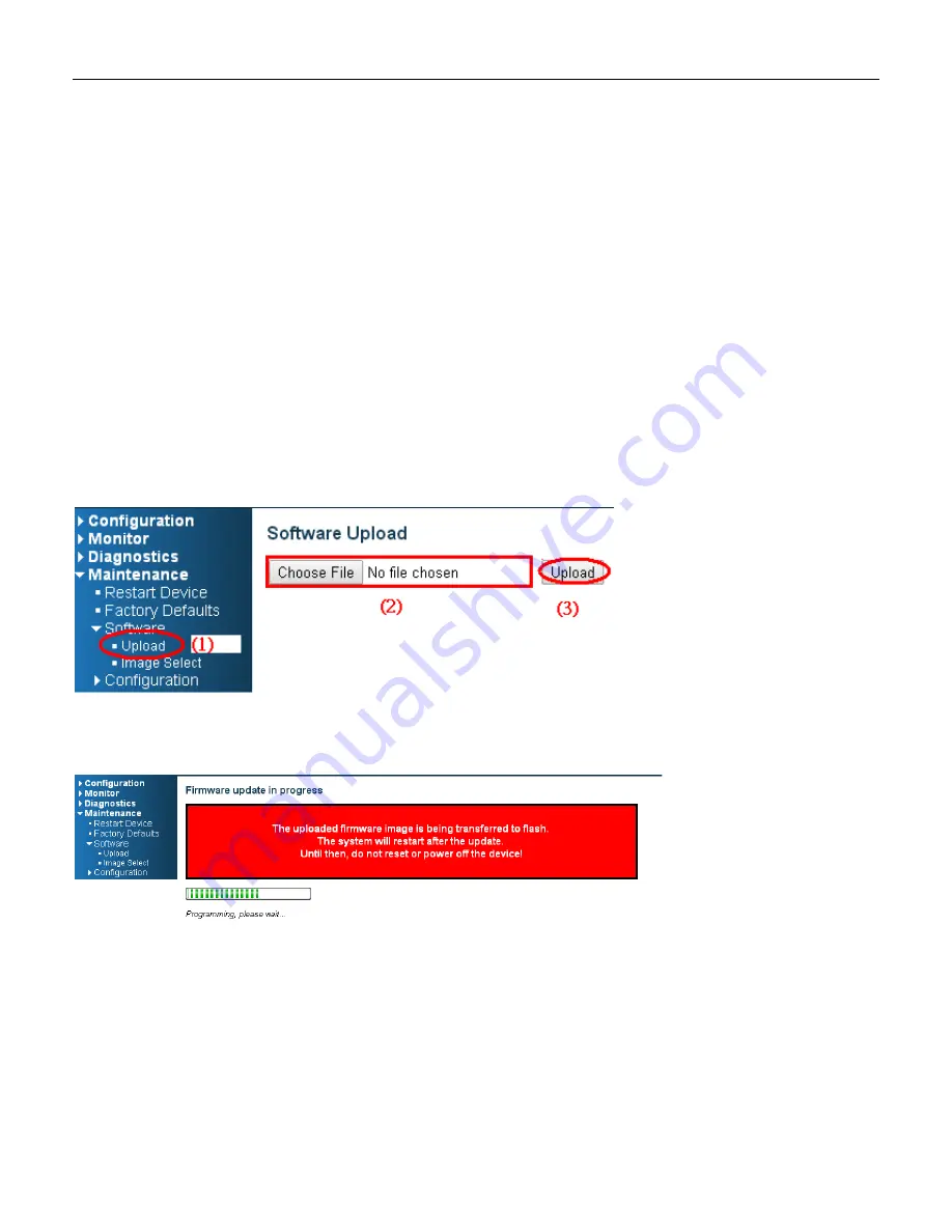
3.12 Upgrade Software
1.
In Web UI, go to “Maintenance
Software
Upload” page.
2.
Select software file, and click “Upload” button.
3.
After starting to upload software to device, please don’t cold/warm start device and wait it auto reboot,
then upgrade finished.
Summary of Contents for RGS Series
Page 7: ...7 Preface Scope Audience Safety Instructions Documentation Conventions ...
Page 9: ...9 Overview Overview Faceplate Panel Introduction ...
Page 13: ...13 Quick Installation Equipment Mounting Cable Connecting Equipment Configuration ...
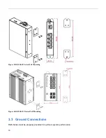
Page 18: ...18 Figure 6 RGS200 12P Series Ground Connections ...
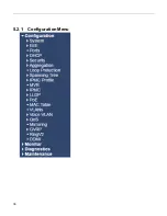
Page 36: ...36 5 2 1 Configuration Menu ...
Page 37: ...37 5 2 2 Monitor Menu ...
Page 38: ...38 5 2 3 Diagnostics Menu 5 2 4 Maintenance Menu ...
Page 54: ...54 5 3 12 Privilege Level This page provides an overview of the privilege levels ...
Page 238: ...238 Click to re start diagnostics with PING ...
Page 252: ...252 台灣 警告使用者 ...

