49
5.3.8 Port
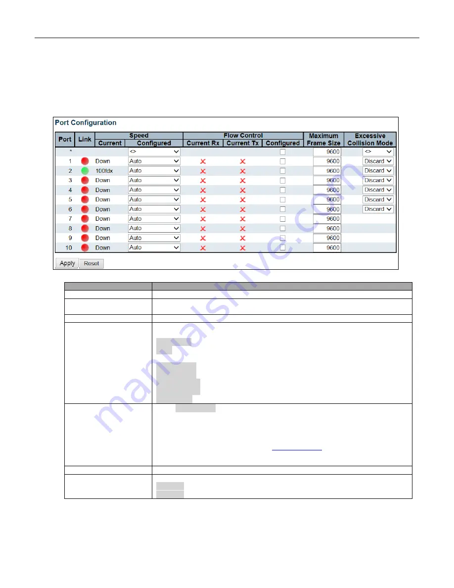
This page displays current port configurations. Ports can also be configured here.
Object
Description
Port
This is the logical port number for this row.
Link
The current link state is displayed graphically. Green indicates the link is up and red
that it is down.
Current Link Speed
Provides the current link speed of the port.
Configured Link Speed
Selects any available link speed for the given switch port. Only speeds supported by
the specific port are shown. Possible speeds are:
Disabled
- Disables the switch port operation.
Auto
- Port auto negotiating speed with the link partner and selects the highest speed
that is compatible with the link partner.
10Mbps HDX
- Forces the cu port in 10Mbps half duplex mode.
10Mbps FDX
- Forces the cu port in 10Mbps full duplex mode.
100Mbps HDX
- Forces the cu port in 100Mbps half duplex mode.
100Mbps FDX
- Forces the cu port in 100Mbps full duplex mode.
1Gbps FDX
- Forces the port in 1Gbps full duplex.
Flow Control
When
Auto Speed
is selected on a port, this section indicates the flow control
capability that is advertised to the link partner.
When a fixed-speed setting is selected, that is what is used. The Current Rx column
indicates whether pause frames on the port are obeyed, and the Current Tx column
indicates whether pause frames on the port are transmitted. The Rx and Tx settings
are determined by the result of the last
Check the configured column to use flow control. This setting is related to the setting
for Configured Link Speed.
Maximum Frame Size
Enter the maximum frame size allowed for the switch port, including FCS.
Excessive Collision
Mode
Configure port transmit collision behavior.
Discard
: Discard frame after 16 collisions (default).
Restart
: Restart backoff algorithm after 16 collisions.
Summary of Contents for RGS Series
Page 7: ...7 Preface Scope Audience Safety Instructions Documentation Conventions ...
Page 9: ...9 Overview Overview Faceplate Panel Introduction ...
Page 13: ...13 Quick Installation Equipment Mounting Cable Connecting Equipment Configuration ...
Page 18: ...18 Figure 6 RGS200 12P Series Ground Connections ...
Page 36: ...36 5 2 1 Configuration Menu ...
Page 37: ...37 5 2 2 Monitor Menu ...
Page 38: ...38 5 2 3 Diagnostics Menu 5 2 4 Maintenance Menu ...
Page 54: ...54 5 3 12 Privilege Level This page provides an overview of the privilege levels ...
Page 238: ...238 Click to re start diagnostics with PING ...
Page 252: ...252 台灣 警告使用者 ...


