82
5.3.32 Access Control List
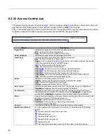
This page shows the Access Control List (
s defined on this switch. Each row
describes the ACE that is defined. The maximum number of ACEs is
256
on each switch.
Click on the lowest plus sign to add a new ACE to the list. The reserved ACEs used for internal protocol, cannot
be edited or deleted, the order sequence cannot be changed and the priority is highest.
Object
Description
Ingress Port
Indicates the ingress port of the ACE. Possible values are:
All
: The ACE will match all ingress port.
Port
: The ACE will match a specific ingress port.
Policy / Bitmask
Indicates the policy number and bitmask of the ACE.
Frame Type
Indicates the frame type of the ACE. Possible values are:
Any
: The ACE will match any frame type.
EType
frames. Note that an Ethernet Type based
ACE will not get matched by IP and ARP frames.
: The ACE will match ARP/RARP frames.
IPv4
: The ACE will match all IPv4 frames.
: The ACE will match IPv4 frames with ICMP protocol.
: The ACE will match IPv4 frames with UDP protocol.
: The ACE will match IPv4 frames with TCP protocol.
IPv4/Other
: The ACE will match IPv4 frames, which are not ICMP/UDP/TCP.
IPv6
: The ACE will match all IPv6 standard frames.
Action
Indicates the forwarding action of the ACE.
Permit
: Frames matching the ACE may be forwarded and learned.
Deny
: Frames matching the ACE are dropped.
Filter
: Frames matching the ACE are filtered.
Rate Limiter
Indicates the rate limiter number of the ACE. The allowed range is
1
to
16
. When
Disabled
is displayed, the rate limiter operation is disabled.
Port Redirect
Indicates the port redirect operation of the ACE. Frames matching the ACE are
redirected to the port number. The allowed values are
Disabled
or a specific port
number. When
Disabled
is displayed, the port redirect operation is disabled.
Mirror
Specify the mirror operation of this port. Frames matching the ACE are mirrored to the
destination mirror port. The allowed values are:
Enabled
: Frames received on the port are mirrored.
Disabled
: Frames received on the port are not mirrored.
The default value is "Disabled".
Counter
The counter indicates the number of times the ACE was hit by a frame.
Modification Buttons
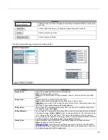
You can modify each ACE (Access Control Entry) in the table using the following
buttons:
: Inserts a new ACE before the current row.
: Edits the ACE row.
: Moves the ACE up the list.
: Moves the ACE down the list.
: Deletes the ACE.
: The lowest plus sign adds a new entry at the bottom of the ACE listings.
Summary of Contents for RGS Series
Page 7: ...7 Preface Scope Audience Safety Instructions Documentation Conventions ...
Page 9: ...9 Overview Overview Faceplate Panel Introduction ...
Page 13: ...13 Quick Installation Equipment Mounting Cable Connecting Equipment Configuration ...
Page 18: ...18 Figure 6 RGS200 12P Series Ground Connections ...
Page 36: ...36 5 2 1 Configuration Menu ...
Page 37: ...37 5 2 2 Monitor Menu ...
Page 38: ...38 5 2 3 Diagnostics Menu 5 2 4 Maintenance Menu ...
Page 54: ...54 5 3 12 Privilege Level This page provides an overview of the privilege levels ...
Page 238: ...238 Click to re start diagnostics with PING ...
Page 252: ...252 台灣 警告使用者 ...


