Chapter 3 Switch Hardware Overview
XS3900-48F User’s Guide
52
1
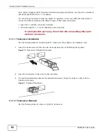
Connect the female end of the power cord to the module power socket.
2
Connect the other end of the cord to a power outlet.
The power modules can be disconnected from the power source individually. Use the following
procedure to disconnect the Switch from a power source.
1
Disconnect the power cord from the power outlet.
2
Disconnect the power cord from the module power socket.
3.3 Switch LEDs
The following table describes the Switch LEDs.
Table 8
Switch LEDs
LED
COLOR
STATUS
DESCRIPTION
SYS
Green
Blinking
The Switch is rebooting and performing self-diagnostic tests.
On
The Switch is on and functioning properly.
Amber
On
The Switch is overheating due to abnormal voltage or fan speed.
Off
The power is off or the Switch is not ready or malfunctioning.
MGMT
LINK
Green
On
The MGMT port is connected at 1000 Mbps.
Amber
On
The MGMT port is connected at 10 or 100 Mbps.
Off
The MGMT port is not up or not connected to an Ethernet device.
ACTIVITY
Green
Blinking
The Switch is transmitting or receiving to/from an Ethernet device
through the MGMT port.
Off
The Switch is not transmitting or receiving to/from an Ethernet
device through the MGMT port.
1-48
Green
Blinking
The port is receiving or transmitting data at 1 or 10 Gbps.
On
The port has a successful 1 or 10 Gbps connection.
Off
This link is disconnected.
49-52
Green
Blinking
The port is receiving or transmitting data at 40 Gbps.
On
The port has a successful 40 Gbps connection.
Off
This link is disconnected.
Summary of Contents for XS-3900-48F
Page 15: ...15 PART I User s Guide ...
Page 16: ...16 ...
Page 48: ...Chapter 2 Tutorials XS3900 48F User s Guide 48 ...
Page 62: ...Chapter 4 The Web Configurator XS3900 48F User s Guide 62 ...
Page 63: ...63 PART II Technical Reference ...
Page 64: ...64 ...
Page 227: ...Chapter 26 VLAN Mapping XS3900 48F User s Guide 227 ...
Page 320: ...Appendix A Common Services XS3900 48F User s Guide 320 ...
Page 332: ...Index XS3900 48F User s Guide 332 ...


