Chapter 9 Interfaces
USG20(W)-VPN Series User’s Guide
204
In this example, virtual Ethernet interface lan1:1 is also removed from the routing table when lan1
is added to br0. Virtual interfaces are automatically added to or remove from a bridge interface
when the underlying interface is added or removed.
9.8.1 Bridge Summary
This screen lists every bridge interface and virtual interface created on top of bridge interfaces. If
you enabled IPv6 in the
Configuration
>
System
>
IPv6
screen, you can also configure bridge
interfaces used for your IPv6 network on this screen. To access this screen, click
Configuration
>
Network
>
Interface
>
Bridge
.
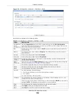
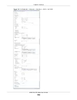
Figure 140
Configuration > Network > Interface > Bridge
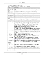
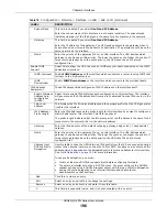
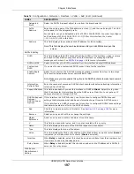
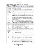
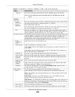
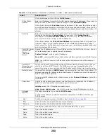
Each field is described in the following table.
241.241.241.241/32
dmz
242.242.242.242/32
dmz
Table 79
Example: Routing Table Before and After Bridge Interface br0 Is Created (continued)
IP ADDRESS(ES)
DESTINATION
IP ADDRESS(ES)
DESTINATION
Table 80
Configuration > Network > Interface > Bridge
LABEL
DESCRIPTION
Configuration / IPv6
Configuration
Use the
Configuration
section for IPv4 network settings. Use the
IPv6
Configuration
section for IPv6 network settings if you connect your USG to an IPv6
network. Both sections have similar fields as described below.
Add
Click this to create a new entry.
Edit
Double-click an entry or select it and click
Edit
to open a screen where you can modify
the entry’s settings.
Remove
To remove an entry, select it and click
Remove
. The USG confirms you want to remove
it before doing so.
Activate
To turn on an entry, select it and click
Activate
.
Inactivate
To turn off an entry, select it and click
Inactivate
.
Create Virtual
Interface
To open the screen where you can create a virtual interface, select an interface and
click
Create Virtual Interface
.
Summary of Contents for ZyWall USG20-VPN
Page 17: ...17 PART I User s Guide ...
Page 18: ...18 ...
Page 99: ...99 PART II Technical Reference ...
Page 100: ...100 ...


