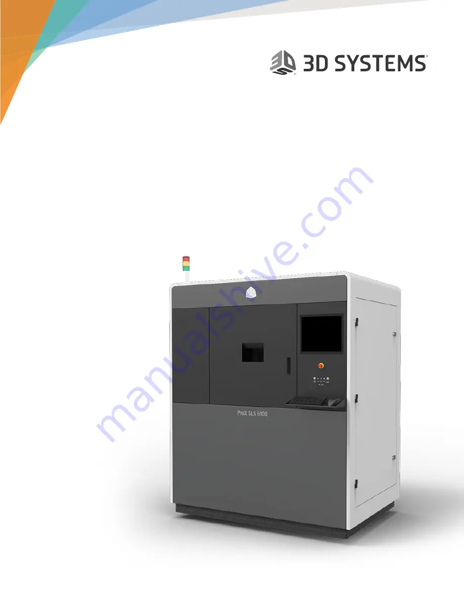
background image

3D Systems, Inc.

ProX® SLS 6100

3D Printer

User Guide 

Original Instructions

Summary of Contents for ProX SLS 6100

Page 1: ...3D Systems Inc ProX SLS 6100 3D Printer User Guide Original Instructions ...

Page 2: ...l Guidelines 7 Training and Instructions 7 Machine Handling 7 Material Handling 7 Laser 7 Alarms and Warnings 7 Safety Symbols and Definitions 8 First Aid Section What to do 9 Burns 9 Reporting Laser Radiation Exposure 9 Electrocution 9 SLS Equipment Safety Features 10 Safety Interlocks 10 SLS System Response if an Interlock Fails 10 Limited Access and Barrier Shielding 10 Other Active Safety Feat...

Page 3: ...inter Application 22 About the Message List Window 22 Restarting a Terminated Build 23 Viewing a Build In Progress 23 Viewing Options on the Toolbar 23 Options on the Viewer Menu 23 Pausing a Build 24 Modifying a Build in Progress 24 Modifying Part and Build Profiles 24 Adding and Deleting Parts and Other Changes 25 Running a Prime Cycle 25 Manual Operations 26 Homing the Part Piston and Roller 26...

Page 4: ...ing the Laser Window 37 Cleaning the IR Sensor Inspect first and olny clean if necessary 37 Cleaning the Black Body 37 Cleaning the Exhaust Port 37 Cleaning and Replacing Filters 38 ProX SLS 6100 Filters 38 Exhaust Processing Module Filters 38 Electrical Enclosure Filter 39 Replacing Electrical Enclosure Filter 39 Transporter Filter Sock Filter 39 Cleaning or Replacing the Transport Filter 39 7 US...

Page 5: ...ge Read this section before you switch on power to any SLS equipment or handle any material Printing Parts with the ProX SLS 6100 This section gives you an outline of the entire part printing process ProX SLS SLS 6100 System Operations This section describes the printer and provides operating instructions for manual control of the machine Machine Operations This section provides an overview of Mat...

Page 6: ...l recycling functions so it pays you back faster ProX SLS 6100 AT A GLANCE F B A D E C Stacklight Indicates the state of the system Print Chamber Area There are two doors in front of the Print Chamber the outer locking door and the inner print chamber door The parts are printed inside the Print Chamber E Stop The Emergency Stop button is a safety mechanism used to shut off the machine in an emerge...

Page 7: ...ou plan to use DuraForm SLS material 3D Systems recommends you install a pneumatic abrasive blast cabinet bead blaster in the part finishing area separate from the ProX 6100 SLS 3D Printer process station room Nitrogen Generator 3D Systems manufactures a High Performance Nitrogen Generator Part Number 104011 02 The generator is ideal for SLS applications 3D Systems Nitrogen Generator Compressed ai...

Page 8: ...pen state Buttons Indicators USB Ports Chamber Lights This button turns the chamber lighting on or off LED Indicators The LED indicators under the monitor indicate the system s power and safety status Each indicator operates as follows Laser Blue LED ON Solid Laser is enabled OFF Laser is not enabled Control Green LED ON Solid System is on and its controller has initialized The system is in RUN mo...

Page 9: ... distributes all the AC power that the system needs Circuits for the various subsystems are located in this module Main Power Disconnect The main power disconnect located on the rear side of the system on the right panel door enables you to turn on and off all power to the system Do NOT position the equipment so that it is difficult to operate this device There is a computer reset button on the ri...

Page 10: ...is in service mode System warning active and or message present on touchscreen E Stop condition or normal Green Print job active System Active not printing manual operations possible E Stop condition or normal Part Transfer Cart Assembly The print cake Extraction Cylinder Part Transfer Tray and Part Transfer Cart are used to remove the print cake from the ProX SLS 6100 print chamber and transport ...

Page 11: ...should only perform tasks they are authorized and certified to complete MACHINE HANDLING Do not try to access service or adjust any components inside any SLS equipment enclosure Do not try to open any panel or door while a machine is running Do not access any area of the machine near the print chamber during printing Use special caution when handling a heated print cake and when dealing with the h...

Page 12: ...se severe burns and blindness Access panels are for service only and should be opened only by certified service personnel ELECTRIC SHOCK HAZARD High voltage electricity is accessible in the vicinity of this sign or behind the access panel High voltage can cause severe burns or death Access panels are for service only and should be opened only by certified service personnel or trained maintenance p...

Page 13: ...ms Circle Rock Hill South Carolina 29730 USA Include the following information in your report Nature of the accident and circumstances surrounding it Where the accident occurred Model and serial number of the machine Number of people involved Any other pertinent information Please send this information to 3D Systems within a day of the accident Electrocution The SLS system contains equipment energ...

Page 14: ...ects too little oxygen in room Print will not start Warning message appears on SLS system display Red Stacklight illuminates Nitrogen generator if in use shuts down Warning message appears on SLS system display Red Stacklight illuminates Laser motors and valves disabled Nitrogen supply shuts off E Stop Only CDA supply shut off System power disabled a Internal panels are for service access only Sev...

Page 15: ...gned to minimize operator exposure to electrical hazards during normal operations All exposed electrical circuits are inside limited access cabinets This is to separate the operator from service and maintenance areas When operating any SLS equipment keep the following electrical safety points in mind Only 3D Systems certified service personnel should operate SLS equipment with access panels or ser...

Page 16: ...le laser radiation is accessible in the vicinity of this sign or behind the access panel Direct and scattered radiation can cause severe burns and eye injury or start a fire Access panels are for service only and should only be opened by certified service personnel DEFEATABLY INTERLOCKED PROTECTIVE HOUSING If you defeat the SLS system laser safety interlocks then open this housing panel or door yo...

Page 17: ... information on specific materials CAUTION Using materials that have not been certified for use in the SLS equipment may cause health or safety hazards and may damage the equipment and void the warranty Material Ignition Information Powdered materials can be flammable and can be ignited by static electricity in a non inert environment Refer to each material s SDS for specific information CAUTION T...

Page 18: ...not required to wear a dust mask or special personal protection equipment unless specifically designated Check the SDS of the material used for the specific precautions you should observe Use the following table of precautions as a general guide Safe Material Handling Guidelines CATEGORY PRECAUTION FIRE HEAT Never smoke or ignite anything around powdered materials Maintain proper clearance from ma...

Page 19: ...deficient make sure you comply with the following items If at any time you feel you are experiencing symptoms of oxygen deprivation leave the area immediately You have received oxygen nitrogen safety training The room is well ventilated at least 4 air exchanges per hour Self contained breathing apparatus is available and easily accessible The room oxygen alarm monitor is functioning and audible Le...

Page 20: ...an Ops mode Move the part piston to its Home position Move the roller to its Home position Move the piston back to its Start position Instructions for each step in this sequence are described next If you re starting the printer from its powered off state do not attempt to start a print before you perform the startup sequence Also never attempt to start a print if the dsp button is not shown in the...

Page 21: ...n grayed out until the DSP is initialized Sinter uses DSP to control SLS system heaters and motion and to communicate with the laser scanning system 2 When you see the DSP button in the taskbar the Sinter application is ready to start a print However you must prepare the chamber before printing the parts Preparing the Print Chamber The following steps are a suggested guideline for preparing the sy...

Page 22: ...ild Profile Editor dialog boxes Parameters control most aspects of how a part is built Modify Build and Part Parameter Values for the Print Job optional 3D Sprint and the ProX6100 are installed with configuration files containing default values for processing a variety of materials You may need to adjust these default parameter values slightly based on your application or desire to customize resul...

Page 23: ...to create the bpz file to be added later to the Print Queue Running the Build After the preceding steps have been completed the printer is ready to print parts 1 Verify that the IR Core temperature value is 77 C 2 If necessary perform an Offline IR Calibration 3 Press the Exit button on the toolbar to exit Manual Ops and return to the main Sinter screen 4 Select Build Start Build select the build ...

Page 24: ...er as even as possible If possible keep scan time under 30 35 seconds Use Build Time estimate and View Layer time to see scan time per layer Geometry s that are closed on all sides except one should be built with the open side up if possible to prevent trapped heat making breakout easier and extending the life of the powder Build Parameters Print bed heaters 6 heaters Q1 Q2 Q3 Q4 Right Inner Left ...

Page 25: ...l Part Bed Surface should be at or below 85C to open Print Chamber door Then move piston to approx 20 mm below current location Open doors Raise Heaters Remove Laser window and Replace with red insert Brush loose powder from liner plate onto part bed Pull roller forward and brush powder from roller bar into part bed return roller to left position Place extraction cylinder in chamber close doors Mo...

Page 26: ...ws you must acknowledge Message Types in Sinter TYPE COLOR DEFINITION Message Black Informational only or tells of a minor error These generally occur when you enter different data than the system expects or when a dependency is not met Advisory Yellow Something occurred that can turn into an alarm condition if not corrected in a specified time Warning Yellow Something serious may occur that you s...

Page 27: ...s not running you exit Build mode You cannot close this window while a build is running but you can minimize it Viewing Options on the Toolbar While the system is in Build mode the Build toolbar appears at the top of the main window as shown Click the Grid button to turn the display of grid marks on or off Click the zoom buttons to expand or contract the scale of the Build Viewer window Options on...

Page 28: ...le button in the Pause Build dialog box Modifying Part and Build Profiles Click the Modify Build Profile or Modify Part Profile button to display a profile editor dialog box Modify parameters as described in the 3D Sprint Help NOTE You can find definitions of the parameters in the 3D Sprint Help In most respects these dialog boxes work just as they do in the 3D Sprint software with the following d...

Page 29: ...ent Z level Changes you make below the plane such as adding or moving parts will not affect the current build although they will be saved and will affect future runs of this build packet Running a Prime Cycle The Prime Cycle can only be run if the user has paused the build Click the Prime Cycle button in the Build Modify dialog to spread powder across the print bed without moving the part piston w...

Page 30: ...er Just before you run your print use the Add Powder dialog box in Man Ops mode to add and level powder in the print chamber Adding powder creates a smooth powder bed on the floor of the print chamber To Add and Level Powder Use the Add Powder button to manually add a layer of powder to the print bed Before you can add a powder layer all these dependencies must be met The roller must be stopped at...

Page 31: ...within the machine NOTE You must perform an initial offline IR calibration to enable automatic real time recalibration during the print If recalibration requires too great an adjustment a message pops up advising you to perform offline calibration again when the print completes NOTE Once you perform an Offline IR calibration the settings are saved in the system An Offline IR calibration does not n...

Page 32: ...d either let it cool down normally or use the nitrogen cooling lid on the side of the ProX MQC System To use the nitrogen cooling lid do the following Immediately after placing the hot print cake in the breakout area of the ProX MQC Single Use System place the nitrogen cooling lid onto the print cake cylinder Then use the cooling lid to do a controlled cooldown for a programmed amount of time the ...

Page 33: ...ke open the outer and inner print chamber doors 12 Slide the Print Cake Tray underneath the cylinder as shown and latch the tray with the pull pins on the cylinder 7 With the handle facing towards you fully insert the extaction cylinder into the print chamber placing it over the print bed 13 If the print cake is light enough it can be moved manually to the ProX MQC System Otherwise use the Part Tr...

Page 34: ...er from the outline of the parts with a spatula and brush Ensure the sifter is running then brush unsintered print cake powder into the sifter When you can easily grasp a part carefully lift it Gently brush off the parts and place them on the breakout area of the ProX MQC Single Use System Part Finishing After Breakout NOTE Consult your Material Guide for full details on part finishing After break...

Page 35: ...X SLS 6100 3D Systems provides a maintenance kit for routine maintenance procedures Many of the tools you need for these procedures can be found in this kit PRINT CHAMBER MAINTENANCE Replacing Light Bulbs in the Process Chamber There are two light bulbs located on the heater assembly of the print chamber If one or both of them burns out contact 3D Systems Field Service Cleaning the Print Chamber B...

Page 36: ...rom the seal around the inside of the print chamber door Use a non ignition vacuum cleaner 7 Clean the door with the tack cloth and vacuum the door and the window If necessary clean the window with ethanol or glass cleaner NOTE Use only soft cloths or paper towels and non abrasive cleaners on the inside of the print chamber window to avoid damaging the coating that prevents the laser beam from esc...

Page 37: ...he belt seals 14 Clean or replace the print chamber filters 15 Clean the part piston and around the part piston seals 16 Return the heater assemblies to their print position 17 Clean the laser window These items must be performed before each build ...

Page 38: ...tant that all impurities are kept off the laser window Impurities can be burned onto the laser window decreasing the laser power available at the print bed Cleaning the laser window is a delicate procedure The laser window can be damaged and may need to be replaced if serious damage occurs Handle the laser window very carefully and follow the cleaning procedure exactly Tools and Supplies Lens tiss...

Page 39: ...de of lens that needs to be cleaned Remove lid and set to the side Cover with lens tissue Remove and clean O Ring Replace into baffle assembly Turn the assembly over Remove lens and set on work table 4 Cover the lens with a lens tissue and turn the assembly over so that the lens comes out 5 Set the lens aside on the work table This will be the side of the O ring that will need to be cleaned the mo...

Page 40: ...Apply acetone to lens Gently wipe lens dry Replace lens Replace top ring and fasten with 2 5mm allen wrench Ensure O Ring is visible and lens is flush with housing Soak up excess acetone with lens tissue 17 After the tissue has soaked up some of the acetone pull it off gently to avoid streaking Discard the tissue 18 Apply a small amount of acetone to the lens again 19 Fold up a lens tissue lengthw...

Page 41: ...y touching the IR sensor head with the tip of the wet swab and rotating the swab 3 Use a dry swab to dry the IR sensor head by gently touching the IR sensor head with the tip of the dry swab and rotating the swab Cleaning the Black Body A clean black body will have a dark matte finish It is important to inspect the black body at least 3 times a week or after 40 hours of print time and clean if nee...

Page 42: ...Active Charcoal Filter Air Processing Module 1 Open the top back doors of the printer 2 Unscrew the filter cover 3 Remove the filters and clean them using a vacuum cleaner or cloth or replace them with new filters 4 Replace the filter cover 5 Close the printer doors Exhaust Processing Module Filters Tools and Supplies Tack cloth New filters Non Ignition vacuum cleaner The exhaust processing module...

Page 43: ...mb screws to unclamp the sock filter 3 Remove the sock filter 4 Turn inside out shake off loose powder and vacuum 5 If necessary replace the filter 6 Replace the filter cover 7 Close the printer door Electrical Enclosure Filter Electrical Enclosure Filter Sock Filter Sock Filter Electrical Enclosure Filter Tools and Supplies Tack cloth New filters Non Ignition vacuum cleaner Replacing Electrical E...

Page 44: ... Blackbody Inspect clean as needed IR sensor Inspect clean as needed Roller clean as needed Chamber door seal inspect and clean as needed Consumable replace as needed PM replace 1yr Sock Filters ProX 6100 AND MQC inspect empty as needed Inspect compressed air condensation oil trap empty if needed NOTE Safety interlocks are located on Overflow cleanout cover Blackbody inspections Inner Print Chambe...

Page 45: ... MAINTENANCE Inspect compressed air condensation oil trap empty if needed Wipe surfaces sift discard unusable powder as needed Disposal container Inspect weekly empty as needed Sifter screen Vacuum after every use Sock filter Inspect weekly clean monthy replace at 6 months 3D PREVENTATIVE MAINTENANCE ANNUAL Replace laser window assembly o rings Replace Chamber door seal Replace chamber lights if n...

Page 46: ...er 2014 Statement about the relevant harmonized standards that have been used or statement about the specifications in relation to which conformity is declared Standard Date of Issue EN 61010 1 2010 EN ISO 12100 2010 EN ISO 13849 1 2015 EN 60825 1 2014 EN 11553 1 2008 EN 55011 2009 A1 2010 EN 61000 6 2 2005 EN 61000 3 3 2013 Additional Information Reserved Name of Person Authorized to compile the ...

Page 47: ...Copyright 3D Systems Inc All rights reserved 3D Systems Inc 333 Three D Systems Circle Rock Hill SC 29730 www 3dsystems com Copyright 3D Systems Inc All rights reserved p n 76 D020 Rev A ...

Reviews: