background image

3M

 Cold Shrink QT-III Silicone 

Rubber Three Core Inverted  

Skirted Termination with High-K 

Stress Relief

For 3-Conductor Type "G" (Ground Wire),  

Copper Tape Shield, Armored Cables
7620-S-INV-3G and 7690-S-INV-3G Series

Instructions

IEEE Std. No. 48

Class I Termination

25/28 kV Class Rated

150 kV BIL - 7620-S-INV-3G Series

200 kV BIL - 7690-S-INV-3G Series

F


CAUTION


 Working around energized systems may cause serious injury or 

death. Installation should be performed by personnel familiar with 

good safety practice in handling electrical equipment. De-energize 

and ground all electrical systems before installing product.

October 2016
78-8124-5866-5-E

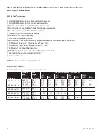
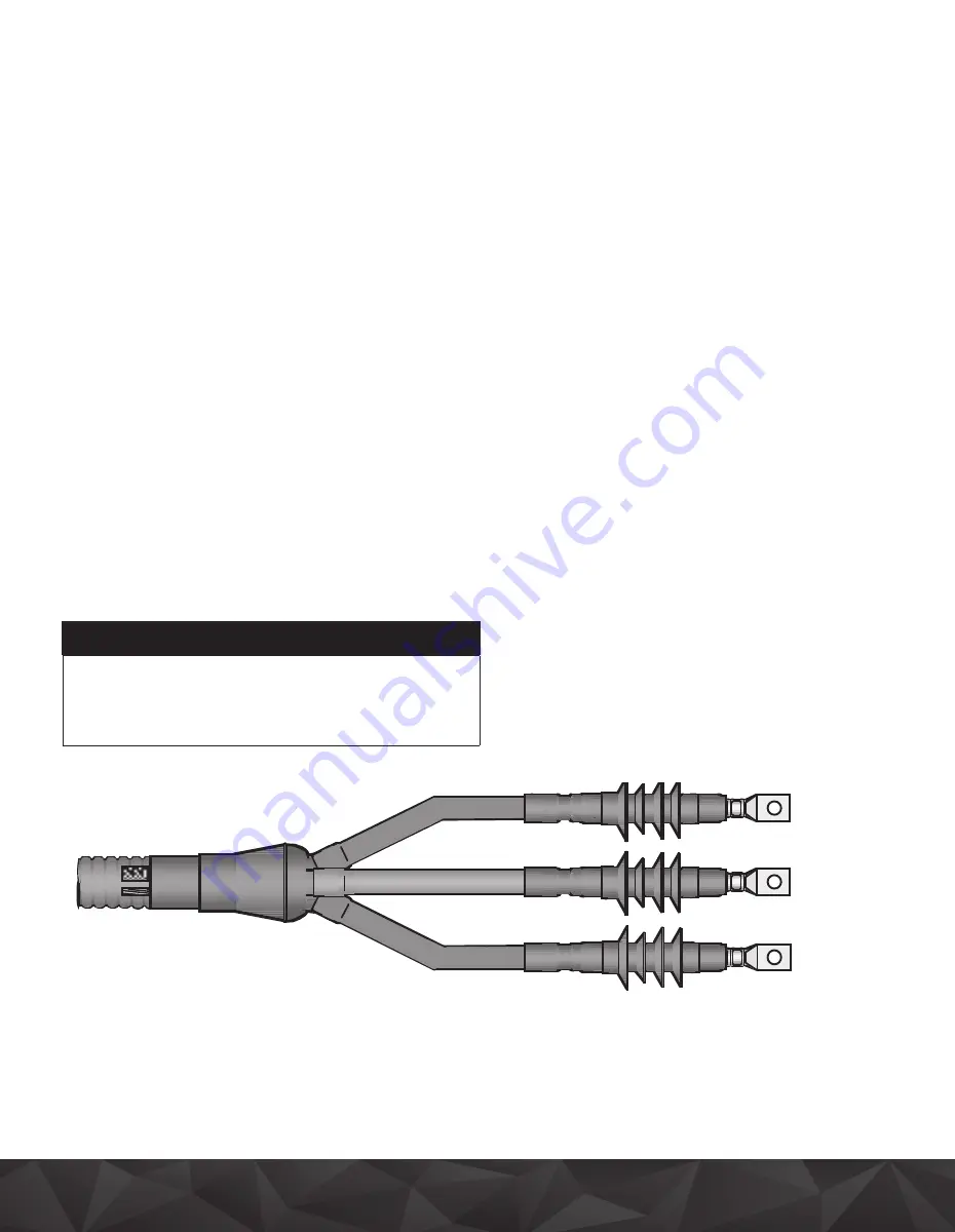
*Picture is representative of the 3M Cold Shrink QT-III Termination 7690 Series. 

The 7620 Series terminations will have only 2 skirts.

Summary of Contents for Cold Shrink QT-III 7620-S-2-INV-3G

Page 1: ... kV BIL 7620 S INV 3G Series 200 kV BIL 7690 S INV 3G Series F CAUTION Working around energized systems may cause serious injury or death Installation should be performed by personnel familiar with good safety practice in handling electrical equipment De energize and ground all electrical systems before installing product October 2016 78 8124 5866 5 E Picture is representative of the 3M Cold Shrin...

Page 2: ... 2 1 Roll Scotch Electrical Shielding Tape 3 3M EMI Copper Foil Shielding Tape 1181 Strips 1 2 x 10 1 3M Cable Cleaning Preparation Kit CC 2 1 Instruction Sheet NOTE Do Not use knives to open plastic bags Kit Selection Table Note Final Determining Factor is Cable Insulation Diameter Kit Number Insulation Range Min Max Inch mm Max Cable O D Inch mm Conductor Size Range AWG and kcmil 5 kV 8 kV 15 kV...

Page 3: ... vary according to specific installation and equipment design requirements They must therefore be determined by the installer and must conform to accepted engineering practices Max phase length 4 ft 121 9 cm termination length from Figure 18 page 14 2 2 Remove cable jacket armor bedding inner sheath and core fillers according to Figure 1 dimensions Secure copper tape shield ends with temporary ban...

Page 4: ... as shown Figure 2 Wrap short center ground braid tail around metallic shield of first cable core Trim excess braid length to prevent overlap Figure 2 Secure ground braid to cable metallic shield using small constant force spring Figure 2 Spring and braid leg should be wrapped in the same direction Cinch twist with hand constant force springs to tighten b Install Second Third Ground Braid Tails Wr...

Page 5: ...jacket material Cut a straight piece to dimension J and wrap it around cable phases beneath ground strap assembly and cable ground wire Secure jacket section in place using Scotch Vinyl Electrical Tape Super 88 wide vinyl tape Figure 3 Note Temporarily remove vinyl tape wrap on ground braid Scotch Vinyl Electrical Tape Super 88 Wide Vinyl Tape Side View Bottom View Ground Wire J Figure 3 ...

Page 6: ... Secure ground braid assembly to cable armor using large constant force spring Figure 4 Once spring has been applied cinch twist with hand to tighten 3 7 Apply one half lapped layer vinyl tape over large constant force spring and cable armor Figure 4 Note Apply vinyl tape to hold down ground strap Figure 4 Vinyl Tape Scotch Electrical Shielding Tape 24 Fill To Level Of Armor High Points Large Cons...

Page 7: ...63 5 mm Figure 5 3 9 Loop cable ground wire back over armor Figure 6 Adjust ground wire position over cable jacket to run parallel with tail of ground braid assembly Note Do not make sharp or tight bends in ground wire Ground wire loop should not extend beyond edge of protective jacket section as shown Do not extend wire loop beyond this edge Rotated View of Cable Figure 6 3 10 Apply two half lapp...

Page 8: ...der Ground Wire Shield Braid Tail Figure 8 3 12 Separate ground wire strands over strips of Scotch Mastic Strip 2230 as shown in Figure 9 Hint Directly over the mastic seal strips lift and bend the ground wire 90 Reverse twist the ground conduc tor to open strands Use a screwdriver to aid in separating the strands On 19 strand wire with reverse twist innerconductors twist ground wire in the opposi...

Page 9: ...acket Note Avoid crossing individual wires at mastic seal location Scotch Mastic Strip 2230 Over Solder Block Section Scotch Mastic Strip 2230 Over Ground Wire Strands Wide Vinyl Tape Scotch Mastic Strip 2230 Over Ground Wire Strands Figure 10 3 14 Wrap two additional strips of Scotch Mastic Strip 2230 directly over previously applied mastic Figure 11 3 15 Cover mastic seal area with two highly st...

Page 10: ... overlap ground wire seal area by approximately 1 4 6 mm To install pull loose core end while unwinding counterclockwise around the cable Figure 12 3 17 Bind cable ground wire and ground braid tail to cable jacket using Scotch Vinyl Electrical Tape Super 88 wide vinyl tape Figure 12 Apply at least eight tape layers and wrap only to width of tape roll 1 4 6 mm Pull Tab Scotch Vinyl Electrical Tape ...

Page 11: ...too far such that boot fingers begin to collapse 4 3 Hold loose neck end core ribbon to one side so that it can not become trapped between cable phases Slide boot assembly over cable end guiding individual cable cores through boot assembly fingers Hint View end of cable through finger cores to ease cable phase insertion 4 4 Slide breakout boot assembly onto cable as far as it will go Large neck en...

Page 12: ...m the chart below determine the correct A dimension for the termination being installed Kit Number Dimension A 7620 S 2 INV 3G 6 25 159 mm 7621 S 2 INV 3G 6 25 159 mm 7622 S 2 INV 3G 8 5 216 mm 7693 S 4 INV 3G 12 0 305 mm 7695 S 4 INV 3G 12 0 305 mm S X B A 1 0 25 mm Overlap Marker Tape Figure 14 5 4 Using scissors trim rejacketing sleeve assembly to length required Figure 15 Cut tubing and inner ...

Page 13: ...ng back on itself for 1 0 25 mm Figure 17 and trim off exposed polyester braid Note Do not damage silicone tubing while cutting Sleeve assembly may be rotated to ease trimming When doing so rotate in the direction of the cable copper tape shield wrap 1 0 25 mm Silicone Tube Fold back Polyester Braid Rejacketing Sleeve over Marker Tape Figure 17 5 8 Slide rejacketing sleeve assembly down until fold...

Page 14: ...A B C D Rejacketing Sleeve Figure 18 Kit Number Dimension A Dimension B Dimension C Dimension D 7620 S 2 INV 3G 6 25 159 mm Lug growth 1 5 38 mm 0 75 19 mm 7621 S 2 INV 3G 6 25 159 mm Lug growth 2 5 64 mm 1 25 32 mm 7622 S 2 INV 3G 8 5 216 mm Lug growth 2 5 64 mm 1 25 32 mm 7693 S 4 INV 3G 12 0 305 mm Lug growth 2 5 64 mm 1 25 32 mm 7695 S 4 INV 3G 12 0 305 mm Lug growth 2 5 64 mm 1 25 32 mm B Lug...

Page 15: ...llic shield and return to starting point Note Do not exceed 0 25 6 mm overlap on 3M EMI Copper Foil Shielding Tape 1181 strip 0 75 19 mm 0 25 6 mm Electrical Grade Vinyl Tape Rejacketing Sleeve Figure 20 6 4 Place a termination installation marker tape at Dimension M measured from semi con leading edge as shown Figure 21 Kit Number Dimension M 7620 S 2 INV 3G 4 0 102 mm 7621 S 2 INV 3G 5 0 127 mm ...

Page 16: ...nto the strands Immediately insert conductor into terminal lug barrel as far as it will go b Ensure that each lug face is parallel to equipment bushing or lug connection interface Figure 22 Last Crimp First Crimp Figure 22 Note Die crimper rotation between consecutive crimps is RECOMMENDED c Crimp terminal lug according to manufacturer recommendations Start at the upper end as shown Figure 22 Remo...

Page 17: ...nue unwinding the core DO NOT PULL OR PUSH ON THE TERMINATION ASSEMBLY WHILE UNWINDING THE CORE e Remove the installation marker tape Termination Base Aligned With Marker Tape Edge Marker Tape White Core Ribbon Counterclockwise Rejacketing Sleeve Figure 23 6 7 Install Cold Shrink skirted insulators a Position skirted insulator over previously installed tubular termination as shown Figure 24 b Alig...

Page 18: ... Warranty Limited Remedy Limited Liability This product will be free from defects in material and manufacture at the time of purchase 3M MAKES NO OTHER WARRANTIES INCLUDING BUT NOT LIMITED TO ANY IMPLIED WARRANTY OF MERCHANTABILITY OR FITNESS FOR A PARTICULAR PURPOSE If this product is defective within the warranty period stated above your exclusive remedy shall be at 3M s option to replace or rep...

Reviews: