background image


GW1118 Series   

Modbus Gateway   

Quick Installation Guide 


3onedata Co., Ltd. 

Address:  3/B, Zone 1, Baiwangxin High Technology 

Industrial Park, Song Bai Road, Nanshan 
District, Shenzhen, 518108, China 

Website: 

www.3onedata.com 

Tel: 

+86 0755-26702688 

Fax: 

+86 0755-26703485 

Package Checklist


Please check whether the package and accessories are intact 
while using the device for the first time. 

1  Modbus gateway × 1 

2  Quick installation guide x1 

3  CD x1 

4  Lug x2 

5  Power adapter x1 

6  Qualify certificate x1 

7  Straight-through cable x1  8  Warranty card x1 
9  Foot pad x4 


If any of these items are damaged or lost, please contact our 
company or dealers, we will solve it ASAP. 

Product Overview


The series products are MODBUS gateway devices. Models 
are as follows: 

Model I  GW1118-8D(3IN1) (8 RS-485/422/232 serial ports + 

+2 100M copper port) 

Model II  GW1118-8DI(RS-485) (8 RS-485/422 serial port 

with iso +2 100M copper port) 

Panel Design


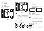
Top view 


Model I


Model II 


Front View 


Model I 


Model II


Rear View 


Model I


Model II 


Bottom View 


1. 

Power indicator 

2. 

Running status indicator 

3. 

Copper port connection indicator 

4. 

Serial port transmission data indicators 

5. 

Serial port receiving data indicators 

6. 

Terminal block for power input 

7. 

Grounding screw 

Summary of Contents for GW1118 Series

Page 1: ...ble x1 8 Warranty card x1 9 Foot pad x4 If any of these items are damaged or lost please contact our company or dealers we will solve it ASAP Product Overview The series products are MODBUS gateway devices Models are as follows Model I GW1118 8D 3IN1 8 RS 485 422 232 serial ports 2 100M copper port Model II GW1118 8DI RS 485 8 RS 485 422 serial port with isolation 2 100M copper port Panel Design T...

Page 2: ...ence installation dimension mark 2 bolt positions on the wall Step 3 Nail M4 screws on the wall and keep 2mm interspace reserved Step 4 Hang the device on two screws and slide downward then tighten the screw to enhance stability mounting ends Wall mounted Device Disassembling Step 1 Device power off Step 2 Unscrew the screw on the wall about 2mm Step 3 Lift the device upward slightly take out the ...

Page 3: ...ing abnormally LINK 1 2 ON Copper port has established an active network connection Blinking Copper port is in a network activity state OFF Copper port has not established an active network connection TX 1 8 OFF No data or abnormal data is being transmitted through serial port Blinking Serial port is transmitting data RX 1 8 OFF Serial port is not receiving data or receiving data abnormally Blinki...

Page 4: ...Running indicator Copper port connection indicator Serial port transmission and receiving data indicator Power supply Input power supply 12 48VDC Access terminal block 3 pin 5 08mm pitch terminal blocks Power consumption Model I No load 1 80W 12VDC Full load 3 90W 12VDC Model II No load 3 16W 12VDC Full load 3 72W 12VDC Working environment Model I Operating temperature 40 75 Storage temperature 40...

Reviews: