background image


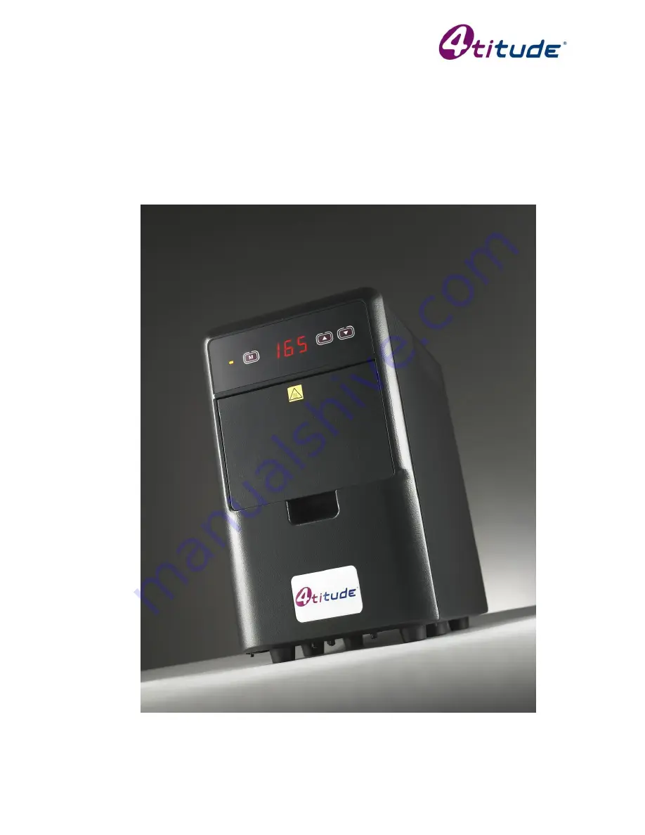
 4s2


Variable Temperature Thermal Sealer Service Manual 


Version: B 


23 September 2010

Summary of Contents for 4s2

Page 1: ...4s2 Variable Temperature Thermal Sealer Service Manual Version B 23 September 2010 ...

Page 2: ...ined in this document is subject to change without notice This document is for information only manufacturer accepts no liability for errors contained herein or for incidental or consequential damages with the furnishing performance or use of this material If not otherwise specified each reference to names or belongings is purely casual and has the purpose to illustrate the product here described ...

Page 3: ...o uk www 4ti co uk Page 2 PAGE INDEX Page 1 TROUBLE SHOOTING GUIDE 3 1 1 Trouble Shooting Guide 3 1 2 Terminology and Abbreviation 3 2 INTRODUCTION 4 2 1 Warnings 4 2 2 General Trouble Shooting Tips 4 3 OPERATION 5 3 1 High Handler Sensor Adjustment 5 3 2 Low Handler Sensor Adjustment 6 3 3 Drawer Sensor Adjustment 8 3 4 Front to Back Adjustment 9 3 5 Left to Right Adjustment 12 4 SPARE PARTS ACCE...

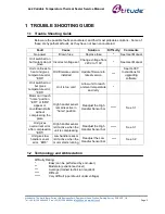
Page 4: ...ion installed Update firmware to latest version See IG 007 Instructions for upgrading software Unit switched on but gives temperature error ER6 Unit is too cold Allow unit to reach ambient temperature and retry Motor can t reach home position ER1 or ER4 appear or countdown starts without compressing the plate High handler sensor remains active in home position Readjust the High Handler Sensor bar ...

Page 5: ...ith the unit disconnected from the mains voltage main power If the procedures request to operate with the power on do NOT touch the PCB or any internal parts that might have a voltage Handle the unit with care If it is necessary to use tools not provided with the 4s2 or to work on faults or parts of the unit not included within this Service Manual please contact your supplier 2 2 General Trouble S...

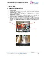
Page 6: ... Check the bar is aligned to the sensor OPT3 on the top of the electronic board If not gently bend the bar to realign it 4 Switch on the unit push down the bar and check the LED LD3 on the top of the electronic board remains off If not gently bend the bar upwards slightly see 2 Figure 1 5 During a compression cycle at ambient temperature check with a calliper the distance from the heater carter an...

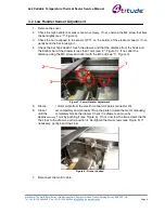
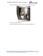
Page 7: ...ar hook doesn t touch the drawer and that the distance from the hook and the bottom bar of the drawer is less than 1mm see 2 Figure 3 If not alter the distance using the M3 screw and lock it with the M3 nut see 3 Figure 3 Figure 3 Lower Handler Adjustment 5 Disconnect the motor cable from the electronic board 2 poles connector J3 6 Close the drawer completely and manually lift up the platen rotate...

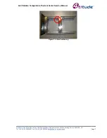
Page 8: ...al Sealer Service Manual 4titude Ltd The North Barn Surrey Hills Business Park Damphurst Lane Wotton Dorking Surrey RH5 6QT UK Tel 44 0 1306 884885 Fax 44 0 1306 884886 info 4ti co uk www 4ti co uk Page 7 Figure 5 L Bar Positioning ...

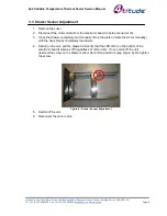
Page 9: ...he electronic board 2 poles connector J3 3 Close the drawer completely and manually lift up the platen rotate the motor manually until the hook blocks completely the drawer 4 Switch on the unit pull the drawer and verify that the LED LD2 on the bottom of the electronic board remains off regardless of unit errors If not switch off the unit unscrew the screw on the drawer sensor bar and re position ...

Page 10: ...see Figure 7 If the front of the PCR microplate is under sealed tighten the screw If the back of the PCR microplate is under sealed loosen the screw Figure 7 Front to Back Screw Adjustment 3 It may also be necessary to adjust the drawer 3 1 Disconnect the motor cable 3 2 Close the drawer completely and manually lift up the platen rotate the motor manually 3 3 Check the pins on the lift are aligned...

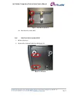
Page 11: ...phurst Lane Wotton Dorking Surrey RH5 6QT UK Tel 44 0 1306 884885 Fax 44 0 1306 884886 info 4ti co uk www 4ti co uk Page 10 Figure 9 Front Panel Adjustment 3 4 Reconnect the motor cable 3 4 2 Units from Serial number 42343 1 Remove the cover 2 Unscrew the 4 screws that fix the lift Figure 10 Figure 10 Lift Screws ...

Page 12: ...ng Surrey RH5 6QT UK Tel 44 0 1306 884885 Fax 44 0 1306 884886 info 4ti co uk www 4ti co uk Page 11 3 Move the lift towards front or back to centralize to the heating block Figure 11 Figure 11 Adjusting the lift s position 4 Screw the 4 screw that fix the lift 5 Execute the operations described in point 3 of the previous paragraph 3 4 1 ...

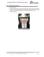
Page 13: ... co uk www 4ti co uk Page 12 3 5 Left to Right Adjustment 1 Remove the cover 2 Locate the lower M4 screw underneath the platen that receives the PCR microplate see Figure 10 If the unit is under sealing on the right loosen the screw and tilt the lift to the left If the unit is under sealing on the left loosen the screw and tilt the lift to the right 3 Re tighten the screw Figure 12 Left to Right A...

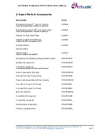
Page 14: ... PCR Plates Incudes 4ti 0612 sealing frame FOC 4ti 0625 Weighted Platen anti roll up tool 4ti 0602 Sealing Frame Only compatible with 4ti 0625 4ti 0612 Replacement cardboard packaging foam inserts SP 0650 PAC Rubber Feet pack of 4 SP 0650 RUF Front Panel light grey includes keypad and circuit board for key pad SP 0650 FPG Outer metal casing light grey SP 0650 OCG Screw Kit for outer metal casing S...

Reviews: