background image

Commercial Gas
High Efficiency Water Heater

s


Cyclone Xi

M O D E L S   C O V E R E D

BTH 120 thru 500 Models

Series 100 and 101

Part No. TC-100

Service Handbook

Part No. 

316586-000

 • Printed in the U.S.A. • 

0509

©2007 A. O. Smith Corporation

COMMERCIAL

Visit the “Information Central” link of
www.hotwater.com for a listing of 
available Service Handbooks.

For additional information contact:

A. O. Smith Water Products Company

A Division of A. O. Smith Corporation

500 Tennessee Waltz Parkway
Ashland City, TN 37015

1-800-527-1953 
www.hotwater.com

Summary of Contents for Cyclone Xi

Page 1: ...Commercial Gas High Efficiency Water Heaters Cyclone Xi M O D E L S C O V E R E D BTH 120 thru 500 Models Series 100 and 101 Service Handbook Part No 316586 000 Printed in the U S A 0509 ...

Page 2: ...O PIPE DIRECT VENT USING OUTSIDE AIR 14 VENT TERMINATION DIRECT VENT ALL MODELS 15 DIRECT VENTING ALL MODELS 16 CONTROL OVERVIEW 17 ADJUSTING TANK TEMPERATURE OPERATING SET POINT DIFFERENTIAL 18 CHANGING THE DISPLAY UNITS 19 FAULT AND WARNING CONDITIONS ADVANCED DIAGNOSTIC INFORMATION 20 ACCESS TO THE CURRENT FAULT OR WARNING 21 FAULT CODES 22 VIEWING THE FAULT HISTORY VIEWING INFORMATION ABOUT TH...

Page 3: ...ols you should not attempt to service this water heater The service handbook is designed to aid in servicing and troubleshooting A O Smith Cyclone Xi BTH commercial water heaters in the field No duplication or reproduction of this book may be made without the express written authorization of the A O Smith Water Products Company The following text and illustrations will provide you with a step by s...

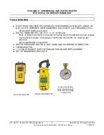
Page 4: ...and FREQUENCY Hz UEi Model DL289 or equivalent DIGITAL MANOMETER 60 W C in 01 increments Note A digital manometer is required for testing pressure switches and can replace a gas pressure gauge draft gauge or slack tube manometer for checking gas pressure UEi model EM200 or equivalent WATER PRESSURE GAUGE w LAZY HAND AND HOSE BIBB CONNECTION THERMOMETER 1 1 16 INCH SOCKET WITH EXTENSION FOR ANODE R...

Page 5: ...n monoxide detectors In the event that the side wall horizontally vented gas fueled equipment is installed in a crawl space or an attic the hard wired carbon monoxide detector with alarm and battery back up may be installed on the next adjacent floor level In the event that the requirements of this subdivision can not be met at the time of completion of installation the owner shall have a period o...

Page 6: ... a pressure gauge manometer to the manifold pressure tap and refer to page 4 for correct pressure b Use this formula to clock the meter Be sure other gas consuming appliances are not operating during this interval Btuh 3600 X H T T Time in seconds to burn 1 cubic foot of gas With a stopwatch read the gas meter and measure the amount of time required for the heater to consume 1 cubic foot of gas H ...

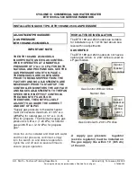
Page 7: ...UIRE THE CORRECT AMOUNT OF INPUT Supply gas pressure to the water heater must not exceed a maximum of 10 5 w c 295kPa for natural gas or 14 w c 3 45 kPa for propane The minimum supply gas pressure is 4 8 w c 1 20 kPa for natural gas and 8 5 w c 2 12 kPa for propane gas Once the unit is installed and filled with water and the inlet pressures confirmed simply turn the switch on and observe operation...

Page 8: ... manometer adjust the gas supply line pressure Gas Pressure table on page 4 2 Check manifold pressure using a pressure gauge manometer connected to the manifold pressure tap on the gas control valve If full rate adjustment is required remove cover screw from top of the gas control valve Using a small screwdriver turn adjusting screw clockwise to increase or counter clockwise to decrease gas pressu...

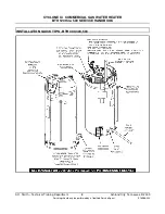
Page 9: ...TER HEATER BTH 120 thru 500 SERVICE HANDBOOK A O Smith Technical Training Department 8 Ashland City Tennessee 2009 Servicing should only be performed by a Qualified Service Agent 316586 000 INSTALLATION QUICK TIPS BTH 300 400 500 ...

Page 10: ... in the vent system the heater is equipped with provision for draining condensate from vent system PH of condensate approximately 3 59 within tolerance for cast iron drains Type venting May be installed Direct Vent draws all fresh air for combustion from and discharges flue gases to the outdoor atmosphere through 2 pipes May be installed Conventional Vent uses room air for combustion and discharge...

Page 11: ...nt pipe using 4 PVC is 120 feet 36 6m Equivalent feet must include any 90 elbows two 45 elbows equal one 90 elbow Four inch diameter 90 elbows are equivalent to 5 1 5m of pipe VENTING TABLES BTH 300 400 500 Number of 90 Elbows 4 PVC Maximum Feet meters of Pipe ONE 1 65 19 7 m TWO 2 60 18 2 m THREE 3 55 16 7 m FOUR 4 50 15 2 m FIVE 5 45 13 6 m SIX 6 40 12 1 m Vent Length Table Equivalent Feet Meter...

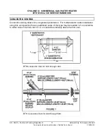
Page 12: ...ed by a Qualified Service Agent 316586 000 Concentric venting allows for a single wall penetration For multiple water heater installation using this vent practice the any additional vents of this type may be located 12 on centerline to either side of the first vent or 12 on centerline vertically above the first vent BTH Concentric Vent for 120 through 300 BTH Concentric Vent for 400 through 500 ...

Page 13: ...CONDENSATE AND SODA POP A The pH of the BTH condensate average 4 5 which is approximately 4 times less concentrated than the limit of 4 3 recommended by the DMA Any water flow in the drain rapidly dilutes the condensate even more A can of leading carbonated cola drink measured a pH of 2 5 which is 300 times more concentrated than the BTH condensate Q WHAT DOES THE Ph SCALE MEAN A The PH value is a...

Page 14: ...R BTH 120 thru 500 SERVICE HANDBOOK A O Smith Technical Training Department 13 Ashland City Tennessee 2009 Servicing should only be performed by a Qualified Service Agent 316586 000 VENTING ALL MODELS SINGLE PIPE POWER VENT USING ROOM AIR ...

Page 15: ...R BTH 120 thru 500 SERVICE HANDBOOK A O Smith Technical Training Department 14 Ashland City Tennessee 2009 Servicing should only be performed by a Qualified Service Agent 316586 000 VENTING ALL MODELS TWO PIPE DIRECT VENT USING OUTSIDE AIR ...

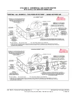
Page 16: ...MINAL LOCATION MUST BE FOLLOWED 1 The intake vent terminal and the exhaust vent terminal must terminate on the same exterior wall and must be located at a minimum of 24 61cm from the vertical centerline of the exhaust vent terminal see Figure 9 In colder climates increasing the 24 61cm minimum will reduce possibility of frost over from side winds blowing exhaust vapors to the air intake of the dir...

Page 17: ...IT IS TO BE SET UP AS A DIRECT VENT THE BALANCE PLATE AND MESH SCREEN MUST BE REMOVED BEFORE GLUING PIPE TO THE CONNECTOR THE INLET VENT PIPE MAY THEN BE GLUED TO THE AIR INTAKE PROVIDED ON THE UNIT Remove the balance plate BTH400 500 only and mesh screen before gluing intake air pipe to the fitting 3 120 250 4 300 500 45 PVC Elbow Two 3 or 4 45 PVC elbows with mesh screens are provided with each ...

Page 18: ... water heater The operating state of the water heater is also indicated graphically by status icons The table of status icons describes graphically operational details of the water heater Below is a legend of all the status icons Status Icon Description The temperature of the water in the tank has fallen and the water heater will now initialize a new heating cycle The temperature of the water in t...

Page 19: ...ture menu Items in this menu allow you to monitor different temperature readings in the tank along with adjusting the Operating Set Point and Differential ACTION From the desktop screen press Menu DISPLAY ACTION From the Main Menu press Select to enter the Temperatures screen DISPLAY ACTION Press Change then use the UP and DOWN buttons to change the temperature Set Point DISPLAY Note This procedur...

Page 20: ...es Celsius for temperature displays This can be found in the Display Settings menu Also in this menu you may adjust how the back light operates and the contrast of the LCD screen ACTION From the Main Menu press the DOWN button to highlight Display Settings then press Select DISPLAY ACTION Use the UP and DOWN buttons to highlight the desired setting Then press Change Again use the UP and DOWN butto...

Page 21: ...gs This is a non safety related condition that the control has detected that may cause the water heater to operate in a less than optimal condition but does not pose a safety concern NOTE When these conditions occur continued heating cycles will continue and the heater will attempt to regulate the water in the tank to the Operating Set Point Example of a Warning Faults This is a safety related con...

Page 22: ...HE CURRENT FAULT OR WARNING When a fault or warning has been detected by the control it will automatically be displayed on the screen and the back light will blink If you choose to leave the current fault or warning by pressing the Back key you can always return to the fault through the display menu ACTION To get to the current fault information screen press Menu DISPLAY ACTION Press the DOWN butt...

Page 23: ... warnings and errors for this commercial gas control 0x0D AC Reversed 0x45 Upper Probe Short 0x46 Lower Probe Short 0x47 Upper Probe Open 0x48 Lower Probe Open 0xB4 Flame Probe Short 0xA9 Flame Detect Error 0xA5 Energy Cut Out ECO 0xA6 Low Gas 0xA7 Blocked Air Intake 0xA8 Blocked Exhaust Event 0xAC Blower Prover Failure 0x1AC Blower Prover Open 0xAE Igniter Current Error 0x1AE Low Igniter Current ...

Page 24: ... long ago the fault occurred ACTION Press the SELECT button for more information DISPLAY ACTION Press the DOWN key to scroll through the fault history If you select a specific fault or warning you may press the VIEW button to view details regarding this fault DISPLAY Viewing Information About the Water Heater The control for this water heater monitors many different aspects of the water to ensure ...

Page 25: ...as to enter the burner chamber 7 The igniter will remain on for a short predetermined time period then will be turned off 8 The control will monitor the flame sense probe to confirm a flame is present If a flame is not verified within predetermined time period the gas valve will immediately be closed and the blower will continue to run for approximately 30 seconds inter purge The control will try ...

Page 26: ...s energized for a pre purge cycle The control will store an error history to show what fault occurred and the time elapsed since the fault When the pre purge is complete power is applied to the igniter for Warm up At the conclusion of the igniter warm up the gas valve will open for 4 seconds If the control senses flame the water heater will fire until the set point is reached If the control fails ...

Page 27: ... cover The CCB is controlled by the settings given through the desk top menu UIM The CCB also monitors all pressure switches the hot surface ignitor tank temperatures the gas valve the anodes and the flame sensor The CCB directly controls blower speed on the BTH 199 and 250 models and indirectly controls blower speed on the BTH 400 500 by means of a Variable Frequency Drive see page 38 Note Improp...

Page 28: ...emoving the cap screw market regulator in the illustration Inlet gas pressure may be read at the inlet pressure tap only if the manual shut off valve gas cock is in the ON position Leaving the knob in the OFF position will not allow the burner to fire and will generate a fault code on the UIM Universal Interface Module The gas control valve on the BTH 150 has a built in pressure regulator The regu...

Page 29: ...THE CORRECT AMOUNT OF INPUT Supply gas pressure to the water heater must not exceed a maximum of 10 5 w c 295kPa for natural gas or 14 w c 3 45 kPa for propane The minimum supply gas pressure is 4 w c 98 kPa for natural gas and 9 w c 2 22 kPa for propane gas Once the unit is installed and filled with water and the inlet pressures confirmed simply turn the switch on and observe operation Cycle the ...

Page 30: ... by connecting to the pressure ports on the valve The manifold pressure on this valve is 0 WC 0kPa when the water heater is running Refer to the gas pressure chart on page 4 Note Tubing shown on pressure connections is installed for manometer connections It is not supplied with the water heater Manifold gas Pressure 0 WC 0kPa Supply gas pressure WARNING Do not attempt adjustments on this gas valve...

Page 31: ...400 The gas control valve has a built in field adjustable pressure regulator The gas valve for the BTH Natural gas model is shown below This is a 24V solenoid operated gas valve Refer to the replacement parts information at the back of this manual for part numbers for Natural and LP gas valves for all BTH 300 400 models ORIFICE CHART BTH 300 400 Model 300 400 Natural 274 314 LP 189 219 24V Solenoi...

Page 32: ...lt in field adjustable pressure regulator The regulator may be adjusted by removing the cap screw marked regulator The adjustment screw is underneath The gas valve for the BTH 500 Natural gas model is shown above This is a 24V solenoid operated gas valve Refer to the replacement parts information at the back of this manual for part numbers for Natural and LP gas valves for all BTH 500 models ORIFI...

Page 33: ...rs BLOCKED OUTLET PROVING SWITCH The blocked outlet proving switch electrical contacts are normally closed The blocked outlet proving switch electrical contacts will open on a rise in pressure Check to see if the condensate is allowed to flow freely from the exhaust elbow and for obstructions in the exhaust venting and exhaust vent terminal Also check that the equivalent feet of vent pipe for the ...

Page 34: ...tins Top View of Pressure Switches BLOCKED INLET PRESSURE SWITCH MODEL PRESSURE All 0 85 WC Normally Closed Open on a fall in Pressure Tolerance 05 WC LOW GAS PRESSURE SWITCH MODEL PRESSURE Natural 4 0 WC LP 8 0 WC Normally Open Close on a Rise in Pressure Tolerance 05 WC BLOCKED OUTLET PRESSURE SWITCH MODEL SWITCH 120N 1 2 WC 150N 0 98 WC 199N 1 06 WC 250N 4 0 WC 120LP 1 3 WC 150LP 1 3 WC 199LP 4...

Page 35: ...tins Top View of Pressure Switches BTH 300 400 500 BLOCKED INLET PRESSURE SWITCH MODEL PRESSURE 300 085 WC 400 1 25 WC 500 1 35 WC Normally Closed Open on a fall in Pressure Tolerance 05 WC LOW GAS PRESSURE SWITCH MODEL PRESSURE Natural 4 6 WC LP 9 0 WC Normally Open Close on a Rise in Pressure Tolerance 05 WC BLOCKED EXHAUST PRESSURE SWITCH MODEL PRESSURE 300 1 15 WC 400 1 39 WC 500 1 77 WC Norma...

Page 36: ...ections for the hot surface igniter and the flame sense rod are shown below Also shown is the burner sight glass These features are typical for all models The new Cyclone Xi commercial water heater is equipped with powered anodes These anodes never need replacement The CCB monitors the current through the anodes and will declare a fault if there is a disconnected wire or if there is no water in th...

Page 37: ...listed between 40 and 70 ohms The minimum igniter current monitored by the CCB is 2 7 amps Once this threshold is met a check mark will appear by the igniter icon in the UIM display FLAME SENSOR This water heater is equipped with an electronic flame sensor The flame sensor senses flame by passing a small electric current through the burner flame This type of flame sensing is also known as flame re...

Page 38: ...al Control Board CCB The rpm of the blower may be measured by attaching a MULTIMETER that has a Hertz Hz setting as shown in the illustration to the right If the Hz signal is within 5 of the numbers in the chart below the reading is normal Model High Speed Hz Low Speed Hz 199 N 133 87 250 N 133 87 199 LP 200 156 250 LP 266 96 Note Removing the plug shown in the illustration will cause the blower t...

Page 39: ...eceives a signal from the central control board that instructs the VFD to transmit the proper frequency to the blower to produce the proper blower speed and proper input Three conditions must be met for the frequency drive to start the blower 1 120VAC must be supplied to the VFD 120VAC input 2 The ignition control board closes an enable circuit terminals LI1 and 15V 3 The ignition control board se...

Page 40: ... the CCB to let the burner operate The frequency numbers displayed may vary slightly with slight variations in the DC voltage generated by the CCB If the water heater exhibits poor run characteristics check the frequency display If the frequency is more than 5 out of range check the DC volt signal at the terminals shown on page 38 Voltage Frequency Speed Instructions VFD Model BTH 400 BTH 500 Inst...

Page 41: ...GAS WATER HEATER BTH 120 thru 500 SERVICE HANDBOOK A O Smith Technical Training Department 40 Ashland City Tennessee 2009 Servicing should only be performed by a Qualified Service Agent 316586 000 WIRING DIAGRAM BTH 120 300 ...

Page 42: ...GAS WATER HEATER BTH 120 thru 500 SERVICE HANDBOOK A O Smith Technical Training Department 41 Ashland City Tennessee 2009 Servicing should only be performed by a Qualified Service Agent 316586 000 WIRING DIAGRAM BTH 400 500 ...

Page 43: ...ormation Central link of www hotwater com for a listing of available Service Handbooks For additional information contact A O Smith Water Products Company A Division of A O Smith Corporation 500 Tennessee Waltz Parkway Ashland City TN 37015 1 800 527 1953 www hotwater com ...

Reviews: