background image

© 2006 McQuay International

DX Cooling Only-

Software Model UV05

Used with AAF-HermanNelson Classroom Unit Ventilator

Model AVV - Floor Mounted

Model AHV - Ceiling Mounted

Model AZV, AZU - Floor Mounted Self Contained Air Conditioner
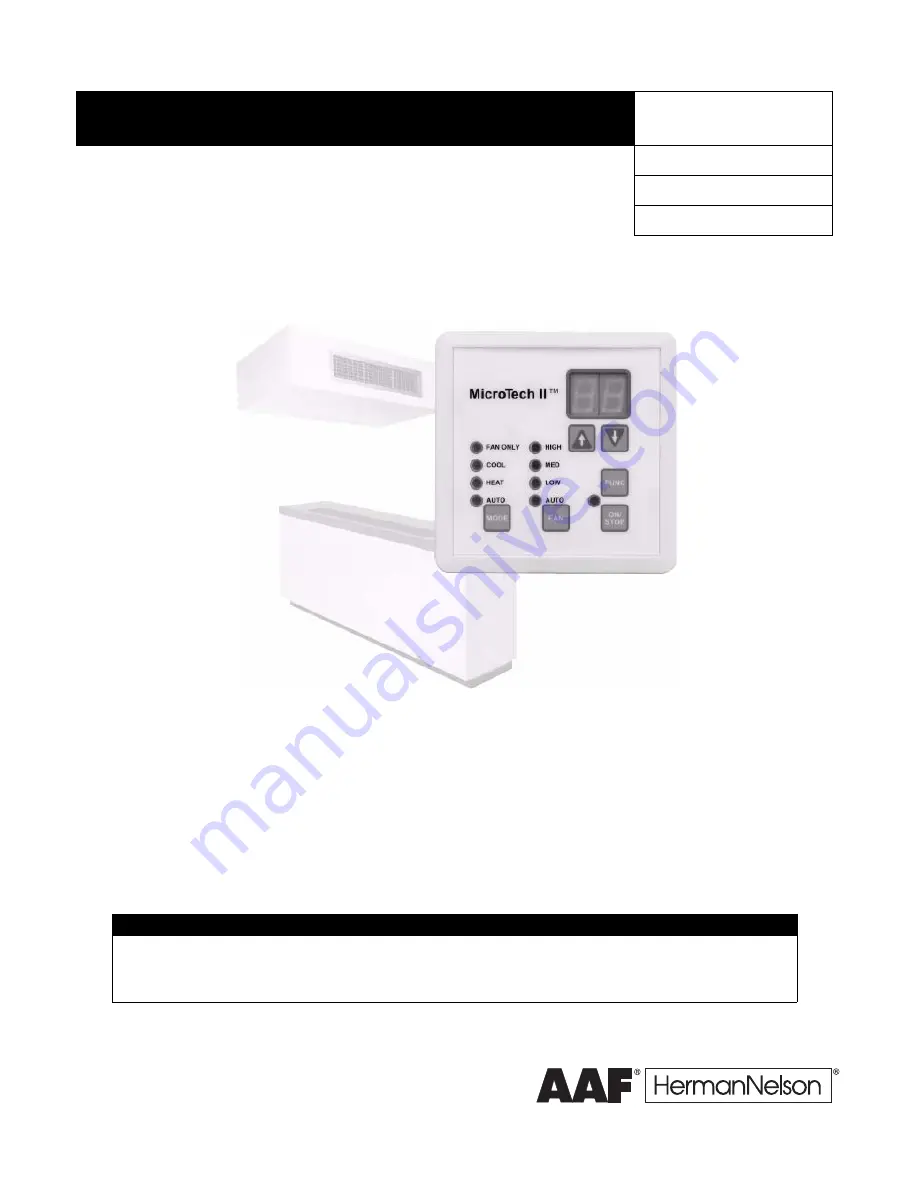
MicroTech II

®

 Unit Ventilator Controls

for AAF

®

-HermanNelson

®

 Classroom Unit Ventilators

Operation Maintenance Manual

OM 751

-1

Group: 

Applied Systems

Part Number: 

OM 751

Date: 

November 2006

IMPORTANT

Before unit commissioning, please read this publication in its entirety.

Develop a thorough understanding before starting the commissioning procedure.

This manual is to be used by the commissioner as a guide. Each installation is unique, only general topics are covered.

The order in which topics are covered may not be those required for the actual commissioning.

Summary of Contents for MicroTech II UV05

Page 1: ...ntilators Operation Maintenance Manual OM 751 1 Group Applied Systems Part Number OM 751 Date November 2006 IMPORTANT Before unit commissioning please read this publication in its entirety Develop a t...

Page 2: ...n 32 Cycle Fan 32 Off Delay 32 Outdoor Air Damper Operation 32 Minimum Position 32 Economizer Operation 32 Networked Space Humidity Sensor Capability 34 Networked Outdoor Humidity Sensor Capability 34...

Page 3: ...ported network variables for each protocol refer to Protocol Data Packet bulletin ED 15065 Table 1 Model specific unit ventilator installation literature Table 2 Protocol specific communication card i...

Page 4: ...nd if not installed and used in accordance with this instruction manual may cause interference to radio communications It has been tested and found to comply with the limits for a Class A digital devi...

Page 5: ...Enthalpy Differential EED Economizer OA Enthalpy Setpoint EES Emergency Heat Setpoint EHS Exhaust Interlock OAD Min Position Setpoint EOAD Outdoor Air Temperature Setpoint EOAT End of Cycle EOC EOC OA...

Page 6: ...O Read Write RW Standby Cooling Setpoint SCS Standby Heating Setpoint SHS Thermal Expansion Valve TXV Unoccupied Cooling Setpoint UCS Unoccupied Heating Setpoint UHS Unit Ventilator UV Unit Ventilator...

Page 7: ...fective heating or cooling temperature set point Effective Set Point Output The display also is used to view and modify UVC parameters as explained in the following sections Note When the UVC is in th...

Page 8: ...each of the fan speeds Fan Speed Command Input Auto Low Medium and High MODE Key Use the MODE key to toggle through the keypad display accessible unit modes Heat Cool Mode Input Auto Heat Cool and Fan...

Page 9: ...and ignore the remote wall sensor set point adjustment knob To use the remote wall sensor set point adjustment knob after you changed the set point offset on the keypad display clear the keypad displa...

Page 10: ...rride Input Set occupancy 0 occupied 1 unoccupied 2 bypass 3 standby Adjusting this variable is intended only for troubleshooting Once you are done cycle unit power to clear this variable and return t...

Page 11: ...ential AHSD Adjust auxiliary heat start differential RW x 1 8 F 1 C A2 Auxiliary Heat End Differential AHED Adjust auxiliary heat stop differential RW x 1 8 F 1 C A3 Auxiliary Heat Configuration Set a...

Page 12: ...into a single control function such as cooling or heating etc States are where all the actual work takes place within each state the UVC enables PI loops and other logic sequences required to control...

Page 13: ...states depending upon the functionality required for each particular mode Each UVC state is assigned a number which can be very helpful when trying to understand which state is currently active within...

Page 14: ...in the OFF mode the UVC is forced into the Emergency Heat mode see Emergency Heat Mode Super State on page 16 The space lighting output continues to operate based upon the current occupancy mode Note...

Page 15: ...External Binary Outputs on page 38 is set to ON If the UVC is not set to another mode within 1 hour fixed the UVC automatically switches to the Fan Only mode see Fan Only Mode State A on page 15 While...

Page 16: ...EHS When Emergency Heat mode becomes active the UVC goes into 100 heating until the space temperature raises to the EHS plus a fixed differential 5 4 F 3 C In the Emergency Heat mode the space fan is...

Page 17: ...diagram Heat State State 5 The Heat state is the normal state during Heat mode When the Heat state becomes active the UVC will within State continually calculate the DATS Discharge Air Temperature Con...

Page 18: ...e 29 Cant Heat State State B The Cant Heat state is a non normal state the UVC can go to when Heat mode is active An IAT or DAT sensor fault during the Heat mode causes the UVC to make this state acti...

Page 19: ...VCLL The CO2 demand controlled ventilation function optional will be active see CO2 Demand Controlled Ventilation optional on page 34 and the OA damper is adjusted as needed to maintain the CO2 set po...

Page 20: ...erature Set Points on page 26 The UVC monitors the DAT to ensure it does not fall below MCLL Figure 14 Econ mech state operation occupied mode and auto fan Mech State State 2 The Mech state is a norma...

Page 21: ...ntain the CO2 set point Low Limit State State F The Low Limit state is a non normal state during Cool mode The Low Limit state typically follows the DA Heat state when the UVC reaches 100 heat and sti...

Page 22: ...Controllers ATS Shutdown Mode Shutdown mode is the equivalent of the Off mode but is an Off mode forced by a network connection When in Shutdown mode the UVC stops all normal heating cooling ventilat...

Page 23: ...rmal UVC mode priority Table 11 Energy hold off Energy hold off Off Off Energized5 Don t care Energy hold off Off Off Pressurize Don t care Don t care Don t care Off Pressurize De pressurize Don t car...

Page 24: ...rmal day time mode of UVC operation During occupied mode the UVC uses the occupied heating and cooling set points the OAD operates normally and by default the IAF remains on Unoccupied Mode The unoccu...

Page 25: ...the tenant override feature For example if the network uses the Occupancy Override Input to force the unit into unoccupied mode then the unit mounted tenant override switch does not operate as expecte...

Page 26: ...aving a relative set point knob Use the keypad display to make adjustments to the value of the Setpoint Offset Input variable See Changing Set Points on page 9 Note The keypad display and the network...

Page 27: ...adjustment dial is used the UVC will effectively write the value of the set point dial to the Space Temp Set Point Input variable Note If a network connection is using the Space Temp Set Point Input v...

Page 28: ...t Occupied Cooling Set Point OCS Standby Cooling Set Point SCS Unoccupied Cooling Set Point UCS Occupied Heating Set Point OHS Standby Heating Set Point SHS Unoccupied Heating Set Point UHS Occupied C...

Page 29: ...charge Air Temperature Setpoint Output Figure 18 Cascading PI loop graphic 1 primary heat Figure 19 Cascading PI loop graphic 2 primary cool economizer PI loops PI loop type Set point Feedback control...

Page 30: ...r Figure 20 Optimized PI loop control Proportional Band The proportional band or proportional action causes the controlled output to changes in proportion to the magnitude of the difference between th...

Page 31: ...small long oscillations occur see Figure 22 In general it is best to start with a relatively large integral time setting the factory default setting is best and adjust to smaller values If you want th...

Page 32: ...occupancy modes and closed during the unoccupied and standby occupancy modes A Triac output is best tested under load using a 24 V relay for verification To verify 1 Put a relay across the Triac outpu...

Page 33: ...enthalpy In this case the UVC is factory set for Economizer Strategy 2 and uses the Temperature Comparison with Enthalpy Comparison Economizer function Note Temperature Comparison with Enthalpy Compar...

Page 34: ...in treating OA not actually needed for ventilation within a space during occupancy levels below maximum design The CO2 DCV function uses a PI loop control to adjust the OA damper above the minimum po...

Page 35: ...or Envelope The compressor envelope protects the compressor from adverse operating conditions that can cause damage and or shortened compressor life by ending compressor operation if coil temperatures...

Page 36: ...The OA fan stops with the compressor Floating Point Actuator Auto Zero Overdrive and Sync The UVC at power up auto zeros all floating point actuators OA damper before going into normal operation to en...

Page 37: ...into unoccupied mode When the contacts open the UVC goes into occupied mode Additional variables can effect occupancy mode and override this binary input See Occupancy Modes on page 24 External Binary...

Page 38: ...ters that can be adjusted to select which function will be used for these outputs when multiple functions are indicated below External Binary Output 1 This output can only be used as a signal for spac...

Page 39: ...an auxiliary heat device The UVC by default is configured to operate a Normally Open auxiliary heat device de energize when heat is required such as a wet heat valve actuator with a spring setup to op...

Page 40: ...or Exhaust Interlock3 3 Field selectable external input options all possible options are shown BI 5 External Input Option 2 Remote Shutdown3 BI 6 External Input Option 1 Unoccupied default BI 7 BI 8 B...

Page 41: ...ibed for each fault Manual reset faults can be reset in one of three ways By cycling the unit power Via the keypad display menu Via the network interface Table 22 Alarm and fault code summary Priority...

Page 42: ...nvelope Fault occurs when the UVC detects compressor operation that exceeded the allowed operating parameters Effect Compressor immediately de energizes Outdoor fan if present de energizes Fault is in...

Page 43: ...e UVC detects open or short conditions from the sensor Effect Outside air damper is forced closed Compressor immediately de energizes Fault is indicated Discharge Air Temp Sensor Failure F7 The Discha...

Page 44: ...fault occurs when the UVC calculates that the total fan run time has exceeded the allowed number of hours since the last filter change Effect Fault is indicated EPROM Memory Indicator EE The EPROM Mem...

Page 45: ...y reading at the sensor location 3 Use the humidity reading from Step 2 determine the expected sensor voltage from Table 24 4 Using a calibrated multi meter measure the actual voltage across the yello...

Page 46: ...4 Using a calibrated multi meter measure the actual voltage across the lead removed from xAI 3 and ground 5 Compare the expected voltage to the actual voltage 6 If the actual voltage value deviates su...

Page 47: ...tpoint OADH this variable will be factory set to 5 open when the unit is ordered with optional CO2 DCV 20 open o2 OAD Min Position Med Speed Setpoint OADM this variable is ignored when the unit is ord...

Page 48: ...t 0 Compressor Enable 0 disable 1 enable 1 C Compressor Minimum On Time 180 sec Compressor Minimum Off Time 300 sec Compressor Cooling Lockout Setpoint CCLO OA temperature below which compressor cooli...

Page 49: ...ems use 327 67 for self contained units 327 67 invalid 327 76 Application Name and Version Label Compressor Start Delay adjust the compressor delay used to prevent multiple compressor units from start...

Page 50: ...training or call 540 248 9646 and ask for the Training Department Warranty All McQuay equipment is sold pursuant to its standard terms and conditions of sale including Limited Product Warranty Consul...

Reviews: