4
1
•
Print switch mode / Command mode
Function
setting
“
prt
2
”
When
the
switch is pressed while the weight value is stable (STABLE indicator is on), the
scale transmits the value.
•
Auto-print mode +/- data / Command mode
Function
setting
“
prt
3
”
The scale transmits the weight value when the display is stable (STABLE indicator is on) and the value
is more than +4d or less than -4d. The next output can be obtained after the value returns to be more
than -4d and less than +4d.
d = minimum display (Refer to “
Specifications
” of the scale instruction manual.)
Even the counting mode uses “d” for judgment.
•
Auto-print mode + data / Command mode
Function
setting
“
prt
4
”
The scale transmits the weight value when the display is stable (STABLE indicator is on) and the value
is more than +4d. The next output can be obtained after the value returns to be less than +4d.
d = minimum display (Refer to “
Specifications
” of the scale instruction manual.)
Even the counting mode uses “d” for judgment.
3.4. Command mode
In the command mode, the scale is controlled by commands that come from the external device such
as a personal computer.
Command list
•
“
Q
” command
Command to request the current weight value.
Command
Q C
R
L
F
Reply
S T , + 0 0 1 2 3 . 4 5 _ k g C
R
L
F
•
“
Z
” command
Same operation as the ZERO switch.
Command
Z C
R
L
F
•
“
T
” command
Same operation as the TARE switch.
Command
T C
R
L
F
Reply to the command
•
When the command cannot be executed, for example, because the scale is unstable, “
I
” will be sent.
Reply
I C
R
L
F
•
If the received command is not for the SC/SE series scale, the scale will send “
?
”.
Reply
? C
R
L
F
•
When “
aCk
0
” is selected, there is no reply except the “
Q
” command.
SCE-03 RS-232C Serial Interface and
Comparator Relay Output
Instruction Manual
1WMPD4002182A
1. Features
•
This interface allows the scale to be connected to a printer or a personal computer.
•
It also allows outputting the comparison results of
HI
,
OK
or
LO
obtained using the comparator
function as a relay signal.
Note: SCE-02
and
SCE-03 can not be installed at the same time.
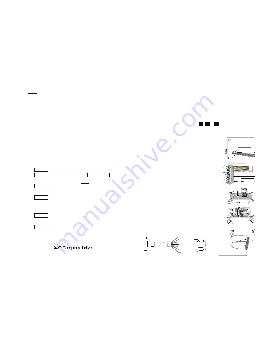
2. Installation Procedure
Note: Before installing the SCE-03 board, be sure to remove
the batteries from the scale.
Step 1 Pass the cable to connect an external device through the hole
on the casing and connect it to the terminal block on the
interface board.
Step 2 Insert the interface board into the casing.
Step 3 Place the waterproof packing on the casing, aligning its holes
with the casing screw holes.
Step 4 Remove the four screws on the option slot panel located on
the bottom of the display.
Step 5 Insert the interface board into the option slot.
Step 6 Secure the casing to the display, using the four screws
provided with the casing.
Step 7 Seal the screw heads with the tabs attached to the waterproof
packing.
•
Cable connection using optional cables (sold separately)
When connecting to an external device with hardware flow
control, communication will be impossible using a cable
without RTS and CTS connected. In that case, connect RTS
and CTS. This will disable hardware flow control, but enable
communication.
•
When the AX-KO3285-320 cable is used, RTS and CTS are
internally connected and the above operation id unnecessary.
•
When the connector of an external device is a D-sub 9-pin
connector, pin 7 is RTS and pin 8 is CTS.
AX-KO3285-320
3-23-14 Higashi-Ikebukuro, Toshima-ku, Tokyo 170-0013 JAPAN
Telephone: [81] (3) 5391-6132
Fax: [81] (3) 5391-6148
Cable (AWG 26~16) to
connect an external device
Waterproof packing
Seal the screw heads
Casing
Screws on the
option slot
6 mm (AWG 26~16)
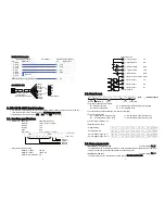
Terminal block
FG
SG
DSR
TXD
RXD
COM
LO
OK
HI
The hole for
the cable
Interface board
Cable (AWG 26~16) to
connect an external device
The hole for
the cable
1. Brown (DCD)
2. Red (RXD)
3. Black (TXD)
4. Yellow (DTR)
5. Green (SG)
6. Blue (DSR)
Shield
RXD
TXD
DSR
SG
FG
SCE-03
Terminal block J1
Optional cable unit to
connect with a PC (3 m)


