


Page 1
Infinity S_Dual V_old_QSG
Version 4.0
© 2021 ABB. All rights reserved.
Infinity S (NE
-
S)
-
48V Power System
Quick Start Guide: 8600243957P
QUICK START GUIDE
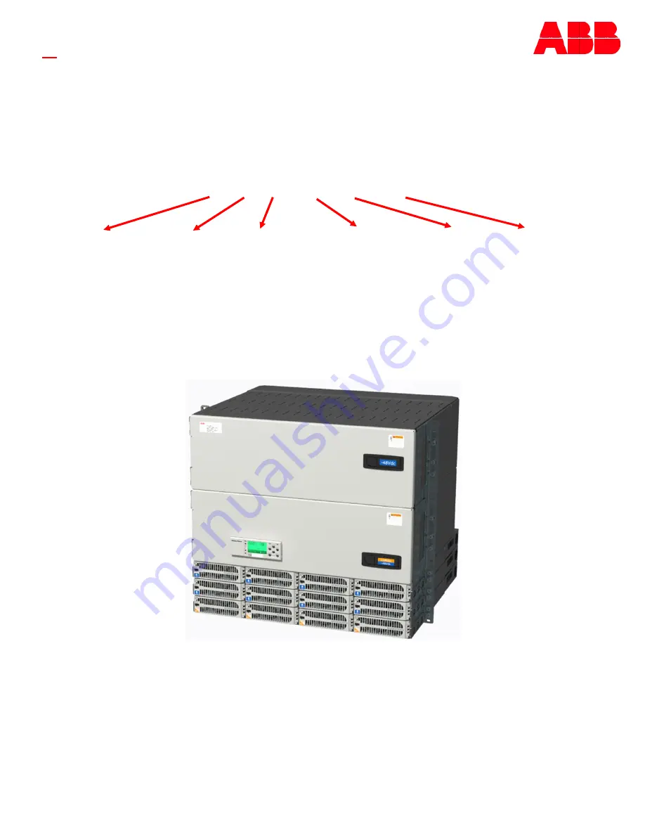
NES4812
-
23
-
AC1
-
PS4
-
DC1E
-
LVBD
Voltages
48YY
48
-
Primary
YY
-
Secondary (12 or 24)
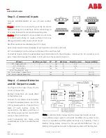
AC input
AC1
-
Molex
AC3
-
IEC 3 20 C 19
AC5
-
Term Block(19
”
only)
AC5H
-
Term Block
AC6
-
3 phase delta Term Block(19
”
only)
AC7
-
3 phase delta wye Term Block
(19”
only)
# of Power Slots
LVBD
option
# of Distribution
Panels (1 or 2)
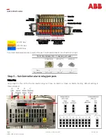
19” / 23”


