background image

Relion

®

 650 SERIES

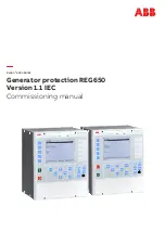
Generator protection REG650

Version 1.1 IEC

Commissioning manual

Summary of Contents for Relion REG650

Page 1: ...Relion 650 SERIES Generator protection REG650 Version 1 1 IEC Commissioning manual ...

Page 2: ......

Page 3: ...Document ID 1MRK 502 035 UEN Issued November 2019 Revision A Product version 1 1 Copyright 2011 ABB All rights reserved ...

Page 4: ...sed or disclosed only in accordance with the terms of such license Trademarks ABB and Relion are registered trademarks of ABB Group All other brand or product names mentioned in this document may be trademarks or registered trademarks of their respective holders Warranty Please inquire about the terms of warranty from your nearest ABB representative ABB AB Substation Automation Products SE 721 59 ...

Page 5: ...ncerning electrical equipment for use within specified voltage limits Low voltage directive 2006 95 EC This conformity is the result of tests conducted by ABB in accordance with the product standards EN 50263 and EN 60255 26 for the EMC directive and with the product standards EN 60255 1 and EN 60255 27 for the low voltage directive The IED is designed in accordance with the international standard...

Page 6: ...product failure would create a risk for harm to property or persons including but not limited to personal injuries or death shall be the sole responsibility of the person or entity applying the equipment and those so responsible are hereby requested to ensure that all measures are taken to exclude or mitigate such risks This document has been carefully checked by ABB but deviations cannot be compl...

Page 7: ...ns 16 3 4 Designed to communicate 18 3 5 Basic IED functions 19 Section 4 Starting up 21 4 1 Factory and site acceptance testing 21 4 2 Commissioning checklist 21 4 3 Checking the power supply 22 4 4 Energizing the IED 22 4 4 1 Checking the IED operation 22 4 4 2 IED start up sequence 22 4 5 Setting up communication between PCM600 and the IED 23 4 6 Writing an application configuration to the IED ...

Page 8: ...ting the test 40 7 3 2 High impedance differential protection HZPDIF 40 7 3 2 1 Verifying the settings 41 7 3 2 2 Completing the test 41 7 3 3 Generator differential protection GENPDIF 41 7 3 3 1 Verifying the settings 41 7 3 3 2 Completing the test 42 7 4 Testing impedance protection functions 42 7 4 1 Underimpedance protection for generators and transformers ZGPDIS 42 7 4 1 1 Distance protection...

Page 9: ... 2 Completing the test 60 7 5 7 Directional underpower protection GUPPDUP 60 7 5 7 1 Verifying the settings 60 7 5 7 2 Completing the test 62 7 5 8 Directional overpower protection GOPPDOP 62 7 5 8 1 Verifying the settings 62 7 5 8 2 Completing the test 63 7 5 9 Accidental energizing protection for synchronous generator AEGGAPC 63 7 5 9 1 Verifying the settings 63 7 5 10 Negative sequence time ove...

Page 10: ...uence function 75 7 8 1 4 Checking the operation of the du dt and di dt based function 75 7 8 1 5 Completing the test 76 7 9 Testing control functions 76 7 9 1 Synchrocheck energizing check and synchronizing SESRSYN 76 7 9 1 1 Testing the synchronizing function 77 7 9 1 2 Testing the synchrocheck check 78 7 9 1 3 Testing the energizing check 80 7 9 1 4 Testing the voltage selection 81 7 9 1 5 Comp...

Page 11: ...tion 91 9 1 3 2 Checking the time synchronization 92 9 1 4 Running the display test 92 9 2 Indication messages 92 9 2 1 Internal faults 92 9 2 2 Warnings 93 9 2 3 Additional indications 93 9 3 Correction procedures 94 9 3 1 Changing and setting the password 94 9 3 2 Identifying IED application problems 94 9 3 2 1 Inspecting the wiring 94 Section 10 Glossary 99 Table of contents Generator protectio...

Page 12: ...6 ...

Page 13: ...ation which is not in service The chapters are organized in chronological order in which the IED should be commissioned 1 2 Intended audience GUID C9B8127F 5748 4BEA 9E4F CC762FE28A3A v6 This manual addresses the personnel responsible for commissioning maintenance and taking the IED in and out of normal service The commissioning personnel must have a basic knowledge of handling electronic equipmen...

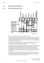
Page 14: ...structure The manual also recommends a sequence for engineering of protection and control functions LHMI functions as well as communication engineering for IEC 60870 5 103 IEC 61850 and DNP3 The installation manual contains instructions on how to install the IED The manual provides procedures for mechanical and electrical installation The chapters are organized in chronological order in which the ...

Page 15: ...hould be used in conjunction with the corresponding communication protocol manual The service manual is not available yet 1 3 2 Document revision history GUID 52A4699C F83B 48F8 BF4E D853043AB731 v1 1 1 Document revision date Product series version History February 2011 1 1 First release A November 2019 1 1 Maintenance release Updated safety information and bug corrections 1 3 3 Related documents ...

Page 16: ...600456 v8 Conventions used in IED manuals A particular convention may not be used in this manual Abbreviations and acronyms in this manual are spelled out in the glossary The glossary also contains definitions of important terms Push button navigation in the LHMI menu structure is presented by using the push button icons for example To navigate between the options use and HMI menu paths are presen...

Page 17: ...n M2366 2 v2 National and local electrical safety regulations must always be followed Working in a high voltage environment requires serious approach to avoid human injuries and damage to equipment M2362 2 v1 Do not touch circuitry during operation Potentially lethal voltages and currents are present M2364 2 v1 Always use suitable isolated test pins when measuring signals in open circuitry Potenti...

Page 18: ... signs IP1503 1 v1 GUID 5D1412B8 8F9D 4D39 B6D1 60FB35797FD0 v2 Whenever changes are made in the IED measures should be taken to avoid inadvertent tripping GUID F2A7BD77 80FB 48F0 AAE5 BE73DE520CC2 v1 The IED contains components which are sensitive to electrostatic discharge ESD precautions shall always be observed prior to touching components M2695 2 v2 Always transport PCBs modules using certifi...

Page 19: ...re making the change 2 4 Note signs IP1497 1 v1 1 1 M19 2 v3 1 1 Observe the maximum allowed continuous current for the different current transformer inputs of the IED See technical data 1MRK 502 035 UEN A Section 2 Safety information Generator protection REG650 13 Commissioning manual Copyright 2011 ABB All rights reserved ...

Page 20: ...14 ...

Page 21: ...EXPDIS 40 Loss of excitation 1 1 OOSPPAM 78 Out of step protection 1 1 LEPDIS Load encroachment 1 1 3 2 Back up protection functions GUID 47D5EAC9 5F4A 4A3D B813 4E50A2BCCDC3 v2 IEC 61850 Function block name ANSI Function description Generator REG650 B01 Gen diff REG650 B05 Gen Trafo diff Current protection OC4PTOC 51 67 Four step directional phase overcurrent protection 2 2 EF4PTOC 51N 67 N Four ...

Page 22: ...FRC 81 Rate of change frequency protection 2 2 3 3 Control and monitoring functions GUID C4EC0541 2883 4185 90AB BAEB25A5E249 v2 IEC 61850 Function block name ANSI Function description Generator REG650 B01 Gen diff REG650 B05 Gen Trafo diff Control SESRSYN 25 Synchrocheck energizing check and synchronizing 1 1 QCBAY Bay control 1 1 LOCREM Handling of LR switch positions 1 1 LOCREMCTRL LHMI control...

Page 23: ...rable logic blocks set reset memory flip flop gate 40 40 RSMEMORY Configurable logic blocks reset set memory flip flop gate 40 40 FXDSIGN Fixed signal function block 1 1 B16I Boolean 16 to Integer conversion 16 16 B16IFCVI Boolean 16 to Integer conversion with logic node representation 16 16 IB16A Integer to Boolean 16 conversion 16 16 IB16FCVB Integer to Boolean 16 conversion with logic node repr...

Page 24: ... 16 16 ETPMMTR Function for energy calculation and demand handling 3 3 3 4 Designed to communicate GUID 22F345AB 6250 40E7 9B80 36EA4D8EDA62 v2 IEC 61850 Function block name ANSI Function description Generator REG650 B01 Gen diff REG650 B05 Gen Trafo diff Station communication IEC 61850 communication protocol LAN1 1 1 DNP3 0 for TCP IP communication protocol LAN1 1 1 IEC61870 5 103 IEC60870 5 103 ...

Page 25: ...ing groups 1 TESTMODE Test mode functionality 1 CHNGLCK Change lock function 1 TERMINALID IED identifiers 1 PRODINF Product information 1 PRIMVAL Primary system values 1 SMAI_20_1 12 Signal matrix for analog inputs 2 3PHSUM Summation block 3 phase 12 GBASVAL Global base values for settings 6 ATHSTAT Authority status 1 ATHCHCK Authority check 1 FTPACCS FTP access with password 1 DOSFRNT Denial of s...

Page 26: ...20 ...

Page 27: ...res that the acceptance testing has been performed and that the application configuration is verified Maintenance testing is a periodical verification that the IED is healthy and has correct settings depending on changes in the power system There are also other types of maintenance testing 4 2 Commissioning checklist GUID 93D14E4E 5DDE 4D37 84A6 2DF0656AB73D v2 Before starting up commissioning at ...

Page 28: ... power supply of the IED to start it up This could be done in number of ways from energizing a whole cubicle to energizing a single IED Set the IED time if no time synchronization source is configured Check also the self supervision function in Main menu Diagnostics Internal events or Main menu Diagnostics IED status General menu in local HMI to verify that the IED operates properly 4 4 2 IED star...

Page 29: ...ing mask must be set via the LHMI for each available Ethernet interface in the IED Each Ethernet interface has a default factory IP address when the complete IED is delivered This is not given when an additional Ethernet interface is installed or an interface is replaced The default IP address for the IED front port is 10 1 150 3 and the corresponding subnetwork mask is 255 255 255 0 which can be ...

Page 30: ...he IED are received on the Tx pin on the PC Thus straight standard Ethernet cable can be used When a computer is connected to the IED and the setting DHCPServer is set to On via the local HMI path Main menu Configuration Communication TCP IP configuration 1 ETHFRNT DHCPServer the IEDs DHCP server for the front port assigns an IP address for the computer The computer must be configured to obtain it...

Page 31: ...utomatically if the parameter DHCPServer is set to On in the IED IEC09000358 1 en vsd IEC09000358 V1 EN US Figure 6 Select Obtain an IP address automatically 5 Select Use the following IP address and define IP address and Subnet mask if the front port is used and if the IP address is not set to be obtained automatically by the IED see Figure 7 The IP address must be different from the IP address c...

Page 32: ...ation must be written to the IED When writing an application configuration to the IED the IED is automatically set in the configuration mode When the IED is set in the configuration mode all functions are blocked The red Trip LED on the IED flashes and the green Ready LED is lit while the IED is in the configuration mode When the writing procedure has completed the IED is automatically set into no...

Page 33: ...s is properly connected to the station earth and only at one electrical point Insulation resistance check CT and VT connectors are pre coded and the CT and VT connector markings are different For more information see the installation manual Both the primary and the secondary sides must be disconnected from the line and the IED when plotting the excitation characteristics 4 8 Checking VT circuits M...

Page 34: ...for operation By pulling in all cables verify that the contact sockets have been crimped correctly and that they are fully inserted Never do this with current circuits in service Current circuit 1 Verify that the contacts are of current circuit type 2 Verify that the short circuit jumpers are located in the correct slots Voltage circuit 1 Verify that the contacts are of voltage circuit type 2 Chec...

Page 35: ...ng optical connections M16022 2 v5 Check that the Tx and Rx optical connections are correct An IED equipped with optical connections requires a minimum depth of 180 mm for plastic fiber cables and 275 mm for glass fiber cables Check the allowed minimum bending radius from the optical cable manufacturer 1MRK 502 035 UEN A Section 4 Starting up Generator protection REG650 29 Commissioning manual Cop...

Page 36: ...30 ...

Page 37: ...ont port the parameter GOOSE in Main menu Configuration Communication Station communication IEC61850 8 1 must be set to Front To enable GOOSE communication via rear port the parameter GOOSE must be set to LAN1 5 2 Verifying the communication SEMOD172108 24 v5 Connect your PC to the nearby switch and ping the connected IED and the Substation Master PC to verify that the communication is working up ...

Page 38: ...32 ...

Page 39: ...hieved The IEDs in the 650 series can have between 1 to 4 individual parameter setting groups prepared with full sets of different parameters for all functions The purpose of these groups is to be able to handle different power system load conditions to optimize the parameters settings of the different functions for these different power systems conditions for example summer winter and day night P...

Page 40: ...ocal remote control state changes are saved A mechanism for limiting the number of writings per time period is included in the IED to prevent the flash memory to be worn out due to too many writings As a consequence it may take up to an hour to save changes If the auxiliary power is interrupted before a change is saved that change is lost 6 2 Activating test mode M11412 2 v6 Put the IED into the t...

Page 41: ...transients are given a chance to decay before the trip circuits are restored When the latches are released the handle can be completely withdrawn from the test switch restoring the trip circuits to the protection IED If a test switch is not used take measures according to provided circuit diagrams Never disconnect the secondary connection of a current transformer circuit without short circuiting t...

Page 42: ...t to No and Yes respectively Remember that a function is also blocked if the BLOCK input signal on the corresponding function block is active which depends on the configuration Ensure that the logical status of the BLOCK input signal is equal to 0 for the function to be tested Event function blocks can also be individually blocked to ensure that no events are reported to a remote station during th...

Page 43: ... to verify that phases are correctly connected If some setting deviates check the analog input settings under Main menu Configuration Analog modules Measured values such as current and voltages as well as active reactive and apparent power power factor phase angles as well as positive and negative and zero sequence currents and voltages are available in the local HMI under Main menu Tests Function...

Page 44: ...rm and blocking signals Use the disturbance handling tool in PCM600 to evaluate that the protection function has received the correct data and responded correctly signaling and timing Use the event viewer tool in PCM600 to check that only expected events have occurred Section 6 1MRK 502 035 UEN A Testing IED operation 38 Generator protection REG650 Commissioning manual Copyright 2011 ABB All right...

Page 45: ...re cleared Setting OpModeTest for the control of the disturbance recorder during test mode are located on the local HMI under Main menu Settings IED Settings Monitoring Disturbance report 1 DRPRDRE 7 2 Identifying the function to test in the technical reference manual M11748 2 v3 Use the technical manual to identify function blocks logic diagrams input and output signals setting parameters and tec...

Page 46: ...the transformer differential protection 11 Finally check that trip information is stored in the event menu 12 If available on the test set a second harmonic current of about 20 assumes 15 setting on I1 I2ratio parameter can be added to the fundamental tone in phase L1 Increase the current in phase L1 above the start value measured in step 6 Repeat test with current injection in phases L2 and L3 re...

Page 47: ... U Alarm and measure the alarm time 9 Check that trip and alarm outputs operate accordingly to the configuration logic 10 Finally check that start and alarm information is stored in the event menu and if a serial connection to the SA is available verify that the correct and only the required signals are presented on the local HMI and on the SCADA system Information on how to use the event menu is ...

Page 48: ... value measured in step 3 Repeat test with current injection in phases L2 and L3 respectively Fifth harmonic blocking can be tested in a similar way The balancing of currents flowing into and out of the differential zone is typically checked by primary testing 7 3 3 2 Completing the test SEMOD155702 82 v3 Continue to test another function or end the testing by setting the parameter TestMode to Off...

Page 49: ...ed ZxRev Reverse positive sequence impedance setting for zone x where x is 1 3 depending on the zone selected ImpedanceAng The Impedance angle for phase to phase fault in degrees Table 3 Test points for phase to phase Test points X R P1 ZxFwd sin ImpedanceAng ZxFwd cos ImpedanceAng P2 ZxFwd ZxRev 2 sin ImpedanceAng ZxFwd 2 1 cos ImpedanceAng ZxRev 2 1 cos ImpedanceAng P3 ZxFwd ZxRev 2 sin Impedanc...

Page 50: ...wn in figure 10 Read the analog outputs for R and X and check that this reading corresponds to the injected impedance No start or trip signals shall be activated 3 Feed the IED with current and voltage corresponding to the apparent impedance Test 3 as shown in figure 10 Read the analog outputs for R and X and check that this reading corresponds to the injected impedance The signals START and STZ2 ...

Page 51: ... IED for verification of settings as outlined in 6 1 Preparing the IED to verify settings Values of the logical signals for OOSPPAM are available on the local HMI under Main menu Tests Function status Impedance OOSPPAM 78 1 OOSPPAM The Signal Monitoring in PCM600 shows the same signals that are available on the local HMI 7 4 3 1 Verifying the settings GUID C69C1603 7372 4A0C B493 187CAF3B5B2A v1 T...

Page 52: ...y 50 Hz or 60 Hz must be as follows i I t L1 2 2 50 0 2 sin π π IECEQUATION2325 V1 EN US Equation 5 i I t L2 2 2 50 0 2 2 3 sin π π π IECEQUATION2326 V1 EN US Equation 6 i I t L3 2 2 50 0 2 4 3 sin π π π IECEQUATION2327 V1 EN US Equation 7 Where I Ugen 3 ForwardX 14107 A The actual CT ratio must be applied to this primary current so that correct value of the secondary injected current can be calcu...

Page 53: ... sin π π π π π 4 4 3 π IECEQUATION2324 V1 EN US Equation 10 Where I Ugen 3 ForwardX 14107 A The actual CT ratio must be applied to this primary current so that correct value of the secondary injected current can be calculated Expected results As shown in Figure 12 for the test with 49 Hz Periodical trip commands in zone 2 TRIPZ2 with 1 Hz IEC10000141 1 en vsd 0 8 0 6 0 4 0 2 0 0 2 0 4 0 6 0 8 1 0 ...

Page 54: ...S The Signal Monitoring in PCM600 shows the same signals that are available on the local HMI Load encroachment operates on the same measuring principles as the impedance measuring zones Thus it is necessary to follow the same principles as for distance protection when performing the secondary injection tests Measure operating characteristics during constant current conditions Keep the measured cur...

Page 55: ... 4I 1 OC4PTOC The Signal Monitoring in PCM600 shows the same signals that are available on the local HMI 7 5 1 1 Verifying the settings SEMOD56287 72 v4 1 Connect the test set for appropriate current injection to the appropriate IED phases If there is any configuration logic that is used to enable or block any of the four available overcurrent steps make sure that the step under test is enabled fo...

Page 56: ... then set the parameter Blocked to No under Main menu Tests Function test modes Current OC4PTOC 51_67 4I 1 OC4PTOC for the function or for each individual function in a chain to be tested next Remember to set the parameter Blocked to Yes for each individual function that has been tested 7 5 2 Four step residual overcurrent protection EF4PTOC SEMOD53296 3 v6 Prepare the IED for verification of sett...

Page 57: ... or end the testing by setting the parameter TestMode to Off under Main menu Tests IED test mode 1 TESTMODE If another function is tested then set the parameter Blocked to No under Main menu Tests Function test modes Current EF4PTOC 51N67N 4IN X EF4PTOC for the function or for each individual function in a chain to be tested next Remember to set the parameter Blocked to Yes for each individual fun...

Page 58: ...t Tinv kSN Sref I j IECEQUATION2402 V1 EN US Equation 11 6 Compare the result with the expected value The expected value depends on whether definite or inverse time was selected 7 Set the polarizing voltage to zero and increase until the boolean output signal UNREL is activated which is visible in the Application Configuration in PCM600 when the IED is in online mode Compare the voltage with the s...

Page 59: ...tes the START and STDIRIN outputs 3 Measure with angles j RCADir 45 that the measuring element operates when 3I0 3U0 cos RCADir j 3I0 3U0 cos 45 SN 4 Compare the result with the set value Take the set characteristic into consideration see figure 13 and figure 14 5 Measure the operate time of the timer by injecting 1 2 UNRel and a current to get two times the set SN operate value 0 0 3 3 cos test t...

Page 60: ...h the expected value The expected value depends on whether definite or inverse time was selected 7 Continue to test another function or complete the test by setting the test mode to Off 3U0 80 80 Operate area 3I0 en06000652 vsd RCADir 0º ROADir 80º IEC06000652 V2 EN US Figure 15 Example characteristic Non directional earth fault current protection SEMOD175060 117 v4 Procedure 1 Measure that the op...

Page 61: ...re available on the local HMI under Main menu Tests Function status Current TRPTTR 49 T X TRPTTR The Signal Monitoring in PCM600 shows the same signals that are available on the local HMI 7 5 4 1 Checking operate and reset values SEMOD53632 11 v5 1 Connect symmetrical three phase currents to the appropriate current terminals of the IED 2 Set the Time constant 1 Tau1 and Time Constant 2 Tau2 tempor...

Page 62: ...tion in a chain to be tested next Remember to set the parameter Blocked to Yes for each individual function that has been tested 7 5 5 Breaker failure protection CCRBRF M12104 2 v7 Prepare the IED for verification of settings as outlined in 6 1 Preparing the IED to verify settings Values of the logical signals for CCRBRF are available on the local HMI under Main menu Tests Function status Current ...

Page 63: ...1 and back up trip times t2 3 Disconnect AC and START input signals 7 5 5 4 Verifying the re trip mode M12104 36 v5 Choose the mode below which corresponds to the actual case In the cases below it is assumed that FunctionMode Current as set under Main menu Settings IED Settings Current CCRBRF 50BF 1 CCRBRF Checking the case without re trip RetripMode Retrip Off M12104 107 v4 1 Set RetripMode Retri...

Page 64: ...ault current setting IN is below phase current setting IP 1 Set BuTripMode 1 out of 4 2 Apply the fault condition including start of CCRBRF with one phase current below set IP but above IN The residual earth fault should then be above set IN 3 Verify that back up trip is achieved after set time If selected re trip should also appear 4 Disconnect AC and START input signals Checking the case BuTripM...

Page 65: ...e trip without current check is used setting RetripMode No CBPos Check 1 Set FunctionMode Current Contact 2 Apply input signal for CB closed to relevant input or inputs CBCLDL1 2 or 3 3 Apply the fault condition with input signal s for start of CCRBRF The value of current should be below the set value I BlkCont 4 Verify that phase selection re trip if selected and back up trip are achieved after s...

Page 66: ...ther function or end the testing by setting the parameter TestMode to Off under Main menu Tests IED test mode 1 TESTMODE If another function is tested then set the parameter Blocked to No under Main menu Tests Function test modes Current CCRPLD 52PD X CCRPLD for the function or for each individual function in a chain to be tested next Remember to set the parameter Blocked to Yes for each individua...

Page 67: ... V1 EN US Equation 20 L2 2 2 3 L L S U I EQUATION1704 V1 EN US Equation 21 L3 3 3 3 L L S U I EQUATION1705 V1 EN US Equation 22 2 Adjust the injected current and voltage to the set values in of IBase and UBase converted to secondary current and voltage The angle between the injected current and voltage shall be set equal to the set direction Angle1 angle for stage 1 equal to 0 for low forward powe...

Page 68: ...rent corresponding to the mode to be used in the application If a three phase test set is available this could be used for all the modes If a single phase current voltage test set is available the test set should be connected to a selected input for one phase current and voltage Use the formulas stated in Table 4 for the different calculation modes used The set mode Mode can be found under Main me...

Page 69: ...ote the operated value start value 4 Decrease the current slowly and note the reset value 5 Connect a trip output contact to a timer 6 Set the injected current to 200 of the operate level switch on the current and check the time delay 7 Check that all trip and start contacts operate according to the configuration signal matrises 8 Finally check that start and trip information is stored in the even...

Page 70: ...hen testing step 1 if the injected current activates the step 2 6 Decrease the current slowly and note the reset value 7 Connect a trip output contact to a timer 8 Set the current to 200 of the start level of the step 1 switch on the current and check the definite time delay for trip signals TR1 and TRIP Once the measured negative sequence current exceeds the set atart level I2 1 the settable defi...

Page 71: ...ect a TRIP output contact to the timer 6 Set the current to 200 of the operate value switch on the current and check the time delay For inverse time curves check the operate time at a current equal to 110 of the operate current at tMin 7 Check that TRIP and START contacts operate according to the configuration logic 8 Finally check that START and TRIP information is stored in the event menu Inform...

Page 72: ...Slowly decrease the voltage in one of the phases until the START signal appears 4 Note the operate value and compare it with the set value 5 Increase the measured voltage to rated load conditions 6 Check that the START signal resets 7 Instantaneously decrease the voltage in one phase to a value about 20 lower than the measured operate value 8 Measure the time delay for the TRIP signal and compare ...

Page 73: ...n to be tested next Remember to set the parameter Blocked to Yes for each individual function that has been tested 7 6 3 Two step residual overvoltage protection ROV2PTOV SEMOD54358 3 v6 1 1 Prepare the IED for verification of settings as outlined in section Preparing the IED to verify settings Values of the logical signals for ROV2PTOV are available on the local HMI under Main menu Tests Function...

Page 74: ... V Hz 7 Connect a trip output contact to the timer and temporarily set the time delay tMin to 0 5s 8 Increase the voltage and note the V Hz operate value 9 Reduce the voltage slowly and note the reset value 10 Set the time delay to the correct value according to the setting plan and check the time delay tMin injecting a voltage corresponding to 1 2 V Hz 11 Check that trip and alarm contacts operat...

Page 75: ...de of the generator U3T 15 V the magnitude of the third harmonic voltage measured at the terminal side of the generator and ANGLE 180 the angle between the third harmonic voltage phasors U3N and U3T The value of E3 should be close to the following value 2 2 3N 3T 3T E3 U U cos ANGLE U sin ANGLE EQUATION2070 V1 EN US Equation 23 2 Read the value of DU differential voltage The value of DU should be ...

Page 76: ...neutral point measurement only the test is performed by check of this voltage The operate value should be above the measured residual third harmonic voltage in the neutral point at normal operation non faulted generator 7 6 5 3 Completing the test SEMOD158990 34 v3 Continue to test another function or end the testing by setting the parameter TestMode to Off under Main menu Tests IED test mode 1 TE...

Page 77: ... the START value and the definite time delay 2 Supply the IED with three phase voltages at their rated values 3 Slowly decrease the frequency of the applied voltage until the START signal appears 4 Note the operate value and compare it with the set value 5 Increase the frequency until rated operating levels are reached 6 Check that the START signal resets 7 Instantaneously decrease the frequency o...

Page 78: ... especially the START value and the definite time delay 2 Supply the IED with three phase voltages at their rated values 3 Slowly increase the frequency of the applied voltage until the START signal appears 4 Note the operate value and compare it with the set value 5 Decrease the frequency to rated operating conditions 6 Check that the START signal resets 7 Instantaneously increase the frequency o...

Page 79: ...eir rated values 3 Slowly decrease the frequency of the applied voltage with an increasing rate of change that finally exceeds the setting of StartFreqGrad and check that the START signal appears 4 Note the operate value and compare it with the set value 5 Increase the frequency to rated operating conditions and zero rate of change 6 Check that the START signal resets 7 Instantaneously decrease th...

Page 80: ... voltage to the MCBOP binary input The BLKU and BLKZ signals should appear without any time delay All undervoltage dependent functions must be blocked 5 Disconnect the dc voltage from the MCBOP binary input terminal 6 Disconnect one of the phase voltages and observe the logical output signals on the binary outputs of the IED BLKU and BLKZ signals should simultaneously appear BLKU and BLKZ signals ...

Page 81: ...ult with the set value consider that the set value 3U0 is in percentage of the base voltage of the zero sequence operating voltage 7 8 1 4 Checking the operation of the du dt and di dt based function M1405 96 v5 Check the operation of the du dt and di dt based function 1 Simulate normal operating conditions with the three phase currents in phase with their corresponding phase voltages and with all...

Page 82: ...s of its counter value to persistent memory will occur more and more seldom until there is one hour between save operations If the IED is restarted by turning auxiliary power off and back on then up to one hour of counter value increments will be lost This back off algorithm is necessary to avoid wearing out the FLASH memory that is used to save the states values When changing parameter values usi...

Page 83: ... a system with a nominal frequency of 50 Hz but can be directly transferred to 60 Hz SESRSYN can be set to use different phases phase to earth or phase to phase Use the set voltages instead of what is indicated below Figure 17 shows the general test connection principle which can be used during testing This description describes the test of the version intended for one bay Test equipment UMeasure ...

Page 84: ...U Bus Bus voltage input on the IED Testing the voltage difference M2377 194 v4 Set the voltage difference at 15 UBase on the local HMI and the test should check that operation is achieved when the voltage difference UDiffSC is lower than 15 UBase The settings used in the test shall be final settings The test shall be adapted to site setting values instead of values in the example below Test with n...

Page 85: ...DiffM respectively and that operation is blocked when the frequency difference is bigger Test with frequency difference 0 mHz Test with a frequency difference outside the set limits for manual and auto synchronizing check respectively 1 Apply voltages U Line equal to 100 UBase and U Bus equal to 100 UBase with a frequency difference equal to 0 mHz and a phase difference lower than the set value 2 ...

Page 86: ...heck function operates for a low voltage on the U Bus and for a high voltage on the U Line This corresponds to an energizing of a dead bus to a live line 1 Verify the local HMI settings AutoEnerg or ManEnerg to be DBLL 2 Apply a single phase voltage of 30 UBase to the U Bus and a single phase voltage of 100 UBase to the U Line 3 Check that the AUTOENOK and MANENOK outputs are activated 4 Decrease ...

Page 87: ...t M2377 1042 v5 Continue to test another function or end the testing by setting the parameter TestMode to Off under Main menu Tests IED test mode 1 TESTMODE If another function is tested then set the parameter Blocked to No under Main menu Tests Function test modes Control SESRSYN 25 SYNC X SESRSYN for the function or for each individual function in a chain to be tested next Remember to set the pa...

Page 88: ...T must be set 6 Repeat Reset the lockout All functional outputs should reset 7 Deactivate the TRIP signal lockout function set TripLockout Off and the automatic lockout function set AutoLock Offif not needed 7 10 1 3 Completing the test SEMOD54375 203 v5 Continue to test another function or end the testing by setting the parameter TestMode to Off under Main menu Tests IED test mode 1 TESTMODE If a...

Page 89: ... performed with settings Operation On or Operation Off and the function blocked or unblocked The pulse counter value is then checked in PCM600 or on the local HMI 7 13 Exit test mode SEMOD53244 3 v3 The following procedure is used to return to normal operation 1 Navigate to the test mode folder 2 Change the On setting to Off Press the E key and the left arrow key 3 Answer YES press the E key and e...

Page 90: ...84 ...

Page 91: ...cific IED it is type tested according to national and international standards Each individual IED in normal production is individually tested and calibrated before delivery Protection IEDs installed in an apparatus cubicle shall be checked in various ways before delivery Insulation test to check for bad wiring and complete testing of all equipment with injection of currents and voltages is perform...

Page 92: ...ch breaker must be checked individually and it must be verified that the other involved breakers are not tripped at the same time 8 1 3 Periodic maintenance tests SEMOD56517 1 v1 SEMOD56520 5 v3 The periodicity of all tests depends on several factors for example the importance of the installation environment conditions simple or complex equipment static or electromechanical IEDs and so on The norm...

Page 93: ...ize applicable circuit diagrams and have the following documentation available Test instructions for protection IEDs to be tested Test records from previous commissioning and maintenance tests List of valid settings Blank test records to fill in measured values Recording SEMOD56528 14 v2 It is of utmost importance to carefully record the test results Special test sheets covering the frequency of t...

Page 94: ...cessary Trip circuit from trip IEDs to circuit breaker is often supervised by trip circuit supervision It can then be checked that a circuit is healthy by opening tripping output terminals in the cubicle When the terminal is opened an alarm shall be achieved on the signal system after a delay of some seconds However remember to close the circuit directly after the test and tighten the terminal car...

Page 95: ...moved fuse or open miniature circuit breaker with an open connection wrong setting and so on Thus a list should be prepared of all items disturbed during test so that all can be put back into service quickly and without overlooking something It should be put back into service item by item and signed by the responsible engineer 1MRK 502 035 UEN A Section 8 Commissioning and maintenance of the fault...

Page 96: ...90 ...

Page 97: ...nu Diagnostics IED status General 2 Reboot the IED and recheck the supervision events to see if the fault has cleared 3 In case of persistent faults contact ABB for corrective actions 9 1 3 Identifying communication errors GUID 4C589FC4 B122 4F12 8E3D 1B05B4FC5FCE v6 Communication errors are normally communication interruptions or synchronization message errors due to communication link breakdown ...

Page 98: ...ch The Time synch value is Ready when the synchronization is in order Note that the time synchronization source has to be activated Otherwise the value is always Ready 9 1 4 Running the display test AMU0600411 v6 To run the display test either use the push buttons or start the test via the menu Select Main menu Tests LED test Press or simultaneously and All the LEDs are tested by turning them on s...

Page 99: ...he end of the fault indication 9 2 2 Warnings GUID 7BAFA38E 5163 4E01 A7C3 6489B42233C7 v2 The warning message associated with the fault is found in the internal event list in the LHMI menu Main menu Diagnostics Internal events The message includes the date time description and signal state for the fault The current status of the internal fault signals can also be checked via the LHMI in Main menu...

Page 100: ... 2 1 Inspecting the wiring GUID 665B75A6 A074 4A03 ADF1 3D0FAD198E61 v2 The physical inspection of wiring connections often reveals the wrong connection for phase currents or voltages However even though the phase current or voltage connections to IED terminals might be correct wrong polarity of one or more measurement transformers can cause problems Check the current or voltage measurements and t...

Page 101: ...s in the technical data for example 100 mA at 24 V AC DC Output relays especially power output relays are designed for breaking high currents Due to this layers of high resistance may appear on the surface of the contacts Do not determine proper functionality of connectivity or contact resistance by measuring with a regular hand held ohm meter A 1 2 3 4 V GUID BBAEAF55 8D01 4711 A71D BBC76B60BA3D ...

Page 102: ...ctual binary output relay to be operated forced 3 Select the BOn_PO to be operated forced and use and or to operate the actual output relay In PCM600 only the result of these operations can be checked by right clicking the product and selecting Signal Monitoring tool and then navigating to the actual I O board and the binary input in question The activated output signal is indicated with a yellow ...

Page 103: ...t cause problems as it is reduced quickly by the electrical cleaning effect of fritting and thermal destruction of layers bringing the contact resistance back to the mOhm range As a result practically the full voltage is available at the load 1MRK 502 035 UEN A Section 9 Troubleshooting Generator protection REG650 97 Commissioning manual Copyright 2011 ABB All rights reserved ...

Page 104: ...98 ...

Page 105: ... Coupled Voltage Transformer Class C Protection Current Transformer class as per IEEE ANSI CMPPS Combined megapulses per second CMT Communication Management tool in PCM600 CO cycle Close open cycle Codirectional Way of transmitting G 703 over a balanced line Involves two twisted pairs making it possible to transmit information in both directions COMTRADE Standard format according to IEC 60255 24 C...

Page 106: ... architecture ESD Electrostatic discharge FCB Flow control bit Frame count bit FOX 20 Modular 20 channel telecommunication system for speech data and protection signals FOX 512 515 Access multiplexer FOX 6Plus Compact time division multiplexer for the transmission of up to seven duplex channels of digital data over optical fibers G 703 Electrical and functional description for digital lines used b...

Page 107: ...ber in the IED user interfaces The word instance is sometimes defined as an item of information that is representative of a type In the same way an instance of a function in the IED is representative of a type of function IP 1 Internet protocol The network layer for the TCP IP protocol suite widely used on Ethernet networks IP is a connectionless best effort packet switching protocol It provides p...

Page 108: ...PSM Power supply module PST Parameter setting tool within PCM600 PT ratio Potential transformer or voltage transformer ratio PUTT Permissive underreach transfer trip RASC Synchrocheck relay COMBIFLEX RCA Relay characteristic angle RFPP Resistance for phase to phase faults RFPE Resistance for phase to earth faults RISC Reduced instruction set computer RMS value Root mean square value RS422 A balanc...

Page 109: ...erm used to describe how the relay behaves during a fault condition For example a distance relay is underreaching when the impedance presented to it is greater than the apparent impedance to the fault applied to the balance point that is the set reach The relay does not see the fault but perhaps it should have seen it See also Overreach U I PISA Process interface components that deliver measured v...

Page 110: ...l or the earth fault current 3UO Three times the zero sequence voltage Often referred to as the residual voltage or the neutral point voltage Section 10 1MRK 502 035 UEN A Glossary 104 Generator protection REG650 Commissioning manual Copyright 2011 ABB All rights reserved ...

Page 111: ...105 ...

Page 112: ... Substation Automation Products SE 721 59 Västerås Sweden Phone 46 0 21 32 50 00 www abb com substationautomation Copyright 2011 ABB All rights reserved Scan this QR code to visit our website 1MRK 502 035 UEN ...

Reviews: