


Hardware Setup
BIOS Setup
Driver & Utility
Multilingual QIG
Appendix
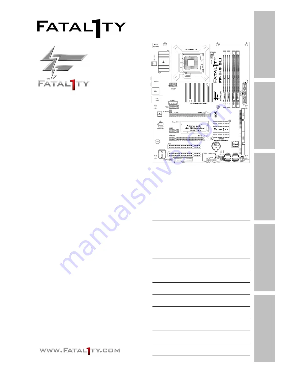
FP-IN9 SLI
Motherboard
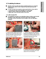
Socket 775
User’s Manual
For more information:
www.abit.com.tw
LGA775 ATX
NB: NVIDIA nForce 650i SLI
SB: NVIDIA nForce 430 SLI
MCP
1066MHz FSB
Dual DDR2 800
NVIDIA Gigabit LAN
4x SATA 3Gb/s
7.1-Channel HD Audio
Silent OTES™ Technology
FPIO LED Lighting
Quick Power & Reset Button
Vista HW Ready
Summary of Contents for Fatal1ty FP-IN9 SLI
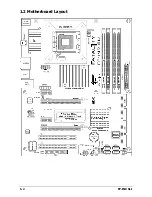
Page 8: ...1 2 FP IN9 SLI 1 2 Motherboard Layout ...
Page 30: ...1 24 FP IN9 SLI For more information www abit com tw ...
Page 60: ...3 8 FP IN9 SLI For more information www abit com tw ...
Page 73: ...Multilingual QIG FP IN9 SLI 4 13 4 13 اﻟﻌﺮﺑﻴﺔ اﻟﻠﻐﺔ اﻟﺴﺮﻳﻊ اﻟﺘﺮآﻴﺐ دﻟﻴﻞ ...
Page 74: ...4 14 FP IN9 SLI 4 14 ﻓﺎرﺳﯽ ﺳﺮﻳﻊ ﻧﺼﺐ راهﻨﻤﺎﯼ ...
Page 88: ...P N 4310 0000 61 Rev 1 00 www abit com tw Johnathan Fatal1ty Wendel ...


