background image

Wallbox eMH1

Installation manual and charging procedure

EN

Summary of Contents for eMH1 WALLBOX

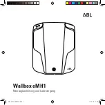
Page 1: ...Wallbox eMH1 Installation manual and charging procedure EN...

Page 2: ...2...

Page 3: ...3 English 4 LANGUAGES FURTHER LANGUAGES www abl de Service Downloads...

Page 4: ...4 Congratulations on your new eMH1 Wallbox Your eMH1 is compact It s easy to use With a maximum of safety...

Page 5: ...ion 26 6 Fixing points 28 7 Power supply entry 31 8 Mounting 34 Electrical installation 9 Preparing for electrical installation 40 10 homeCLU 43 11 Electrical installation 51 12 Start up 58 Charging p...

Page 6: ...6...

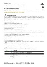
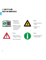
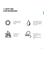
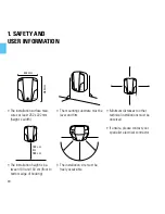
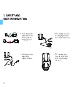
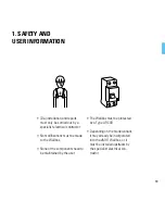
Page 7: ...7 1 Safety and user information 8 SAFETY FIRST...

Page 8: ...tions for operating electrical devices always apply Indicates Dangerous electrical currents Dangers to life and limb Indicates Risks arising from damage to the device Risks for other users Indicates i...

Page 9: ...he installation site must offer protection against rain and running water or other liquids The Wallbox is not situated near a heat source The installation site must offer sufficient air circulation Op...

Page 10: ...height is be tween 140 and 160 cm floor to bottom edge of housing The installation site must be freely accessible The mounting substrate must be level and firm Minimum distances to other technical ins...

Page 11: ...stalled especially If unsure please contact your specialist electrical contractor Ideally cable entry is from the underside of the housing base Above or below surface power supply possible The rated v...

Page 12: ...during the charging process The charging cable and the charging connector must not be driven over The charging cable must not be kinked or twisted The charging cable must be coiled tightly and stored...

Page 13: ...ntractor No modifications must be made to the Wallbox None of the components need to be maintained by the user The Wallbox must be protected by a Type A RCCB Depending on the model variant it may alre...

Page 14: ...t breaker C characteristic The eMH1 Wallbox Complies with all technical safety requirements standards and guidelines Standards guidelines p 86 Represents the current state of technology From October 2...

Page 15: ...r the Wall box and supplied by the manufacturer must be used Accessories p 21 The housing cover of the Wallbox must be locked The Wallbox must be checked regularly for its technically sound condition...

Page 16: ...16...

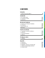
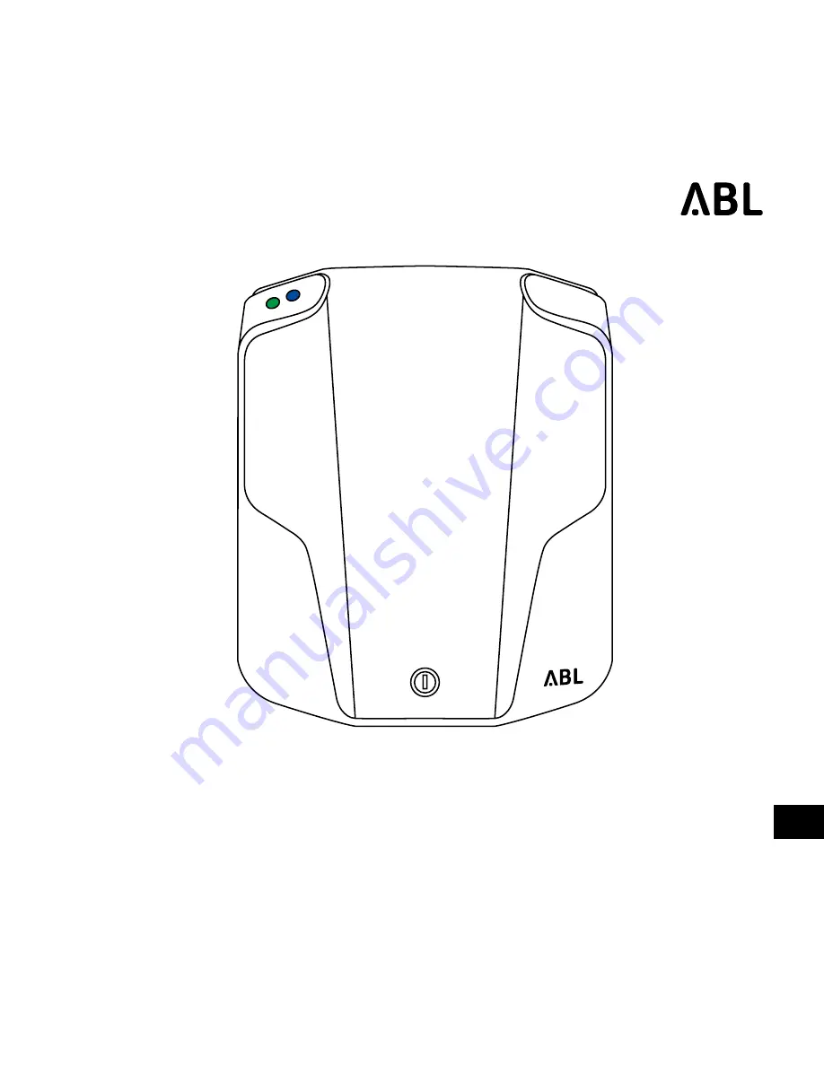
Page 17: ...17 2 Your model variant 18 3 Components included 20 4 Accessories 21 INTRODUCTION...

Page 18: ...18 1 Open the cover 3 p 19 A Cover B Type plate 2 The type plate is located under the cover 2 YOUR MODEL VARIANT A B...

Page 19: ...sal advice D Standard J Read instructions advice E Standard K CE label F Country of manufacture L Barcode 1WXXXX 230 400V 50Hz 16A IP44 IEC 61851 1 IEC 61439 7 ACSEV MADE IN GERMANY ABL SURSUM Bayer E...

Page 20: ...after unpack ing whether all components are included 2 In case of missing components please contact your local distributor eMH1 Wallbox Installation manual 2 x keys 3 x screws countersunk 5 x 60 mm T2...

Page 21: ...urity for the pole and has an integrated tube to protect the power supply The foundation block is made from grade C 25 30 concrete and complies with exposure classes XC4 and XF1 4 x M12 V2A mounting s...

Page 22: ...Mounting plate for all eMH1 Wallboxes USB RS485 Converter To select charging currents via a serial RS485 interface on the EVCC Virtual COM Port USB Type B RS485 RJ12 and MOLEX 5557 incl software and t...

Page 23: ...ent and safe distribution of the existing domestic power sup ply Suitable for load management Further information available at www abl de Installation p 43 with all eMH1 Wallboxes incl control unit ph...

Page 24: ...phase Length ca 4 m IP44 splash protection rating Type 2 Type 2 charging cable acc to IEC 62196 2 20 A 240 415 V AC 3 phase Length ca 7m IP44 splash protection rating Type 2 Type 2 to Type 1 adapter c...

Page 25: ...25 MECHANICAL INSTALLATION 5 Preparing for mechanical installation 26 6 Fixing points 28 7 Power supply entry 31 8 Mounting 34 www abl de Service Downloads This chapter is available on video...

Page 26: ...s Cut power source Electric drill Pliers Tape measure Drill bit 8 mm Utility knife Spirit level Bit Torx T20 Scissors Wall plug 8 x 40 mm Screwdriver Phillips head Pencil Screw countersunk 5 x 60 mm T...

Page 27: ...27 5 PREPARING FOR MECHANICAL INSTALLATION Tools Cut power source 1 Switch off the circuit breaker in the domestic power distribution...

Page 28: ...ower supply Tool Scissors 1 Cut the fixing points as marked Tool Scissors Before drilling check the measurements of the drilling template Marked fixing point Space for power supply A separate drilling...

Page 29: ...g 1 Place the drilling template ver tically on the wall The cut out space marks the opening for the power supply Tool Spirit level 2 Mark the fixing points on the wall Tool Pencil A Cut out space B Po...

Page 30: ...INTS Drilling template Drilling 1 Drill holes where the fixing points are marked Tools Electric drill drill bit 8 mm 2 Insert the wall plugs into the fixing holes Tools Wall plugs 8x40mm Hammer Marked...

Page 31: ...t 1 Open the cover 3 Remove the upper part of the housing from the housing base 2 Loosen the four screws The screws are located in the upper part of the housing Keep the four screws aside Tool Screwdr...

Page 32: ...e stamped plastic lug to allow space for the power supply cable to enter The pre stamped plastic lug is located at the bottom of the housing base Tool Pliers or utility knife This step is only require...

Page 33: ...grommet Housing base 1 Remove the rubber grommet The rubber grommet is located at the bottom of the housing base Cut an opening for the power supply cable into the membrane of the rubber grommet Tool...

Page 34: ...ng points 1 Insert a screw into the upper fixing point The distance between the head of the screw and the wall is 4 mm Tool Electric drill TORX T20 bit Screw countersunk 5 x 60 mm T20 Tape measure 2 p...

Page 35: ...nternal strain relief The strain relief is located on the inside of the housing base above the rubber grommet Tool Electric drill TORX T20 bit A Housing base C Strain relief B Power supply cable 4 p 3...

Page 36: ...36 8 FIXING Upper fixing point Lower fixing points 4 Hang the housing base onto the upper screw...

Page 37: ...int Lower fixing points A A Housing base 1 Screw the housing base to the two lower fixing points Do not distort the housing base material Tools Electric drill TORX T20 bit Screw countersunk 5x60mm T20...

Page 38: ...38 8 FIXING Upper fixing point Lower fixing points 2 Fix the power supply to the internal strain relief Tools Electric drill TORX T20 bit...

Page 39: ...39 ELECTRICAL INSTALLATION 9 Preparing for electrical installation 40 10 homeCLU 43 11 Electrical installation 51 12 Start up 58 www abl de Service Downloads This chapter is available on video...

Page 40: ...40 9 PREPARING FOR ELECTRICAL INSTALLATION Tools Cut power source Voltmeter Pliers Tape measure 2x keys Wire stripper Utility knife Crimp tool Screwdriver Phillips head Components included...

Page 41: ...t be complied with The five golden rules of electrical installation must always be observed 1 Cut power source 2 Secure all cut off devices 3 Verify absence of voltage 4 Ground and short circuit 5 Cov...

Page 42: ...PREPARING FOR ELECTRICAL INSTALLATION Tools Cut power source 1 Switch off the circuit breaker in the domestic power distribution 2 Switch off the RCCB in the Wallbox and or the domestic power distribu...

Page 43: ...ging current required per phase Sum of the charging currents for all charge points Available charging current for each charge point Domestic grid connection type TN IT or TT network Single or 3 phase...

Page 44: ...all charge points ac cording to the respective pattern 2 When connecting charge points to the fuses or terminal blocks rotate the phase sequence one step each time 3 Conventional L1 L2 L3 N busbars s...

Page 45: ...t be connected to the same grounding point otherwise com munication may be lost or the homeCLU unit may be damaged Phase rotation must also be followed if fewer than 6 charge points are connected ensu...

Page 46: ...Wallbox following the same pattern Data cable opening DaisyChain Designation 1 Designation 2 Designation X 1 Insert the data cable through the lower opening in the housing base 2 Connect the data cab...

Page 47: ...cting homeCLU 1 Connect the RJ12 cable with the RJ12 jack The RJ12 jack is located at the left hand edge of the housing base 2 Connect the free end of the RJ12 cable to the RJ12 jack of the RJ12 to US...

Page 48: ...48 10 homeCLU Connecting eMH1 Configuring eMH1 Connecting homeCLU 1 Click on the Refresh ports button 2 Use the drop down menu to select the top COM port 3 Click the Scan bus button 1 2 3...

Page 49: ...ion from the drop down menu 3 Click the write button 1 2 3 The planned connection pattern determines the designations Connection pattern p 44 and in the separate CLU installation diagrams For single p...

Page 50: ...inside the Wallbox The plug in connection is located on the DaisyChain at the upper left hand edge of the housing base next to the PE terminal 3 Crimp the RJ12 plug onto the data cable 4 Connect the...

Page 51: ...ble entry Activation A 3 4 1 Cut the supply cable to the required length Tool Pliers A Power supply cable 2 Strip the oversheath and screen from the power cable beginning at the strain relief Tool Cut...

Page 52: ...52 11 ELECTRICAL INSTALLATION Supply cable Installation Activation 3 Strip the cable Tool Wire stripper 5 Crimp on the ferrule Tool Crimp tool 4 Put ferrule on wires Ferrule 6 7 p 53...

Page 53: ...pply cable into the intended terminal blocks Allocation p 54 7 Screw the cables down in the terminal blocks Tool Screwdriver Phillips head Screws and cables may have become loose during transport All...

Page 54: ...dized Designation Conductor color Connection coding Phase system Phase 1 current carrying con ductor Brown L1 single phase 3 phase Phase 2 current carrying con ductor Black L2 3 phase Phase 3 current...

Page 55: ...stribution 2 In single phase systems the voltage is measured at the openings of the phase and neutral conductor connections In 3 phase systems all phases are measured against each other 400V and all p...

Page 56: ...Place the upper part of the hous ing onto the housing base 4 Fix the upper part of the housing to the housing base using the screws kept for this purpose Tools Screwdriver Phillips head screw kept asi...

Page 57: ...57 11 ELECTRICAL INSTALLATION Supply cable Installation Activation 5 Switch on the RCCB in the Wallbox and or the domestic power distribution 6 Lock the housing cover Tool Key...

Page 58: ...58 12 START UP LED operating states On On Flashing Flashing Off Off...

Page 59: ...59 12 START UP Sequence S1 The Wallbox is starting up Both LEDs are flashing Both LEDs are Off 1 Check that the LED indicators of the Wallbox display this operating state 2 p 60 3 p 61 1sec 1sec...

Page 60: ...on the software version Then the blue LED flashes according to the software version 2 Check that the LED indicators of the Wallbox display this operating state Example For the 2 4 software ver sion t...

Page 61: ...lashes every 5 seconds The blue LED is continuously Off 3 Check that the LED indicators of the Wallbox display this operating state The vehicle may be connected Sequence A The Wallbox is ready for use...

Page 62: ...62...

Page 63: ...comprehensive operating manual contains the following chapters Error messages and resolving errors Taking energy consumption readings Testing the RCCB Taking the device temporarily or permanently out...

Page 64: ...64 13 CHARGING Before the charging procedure During the charging procedure After the charging procedure LED operating states On On Flashing Flashing Off Off...

Page 65: ...D indicators of the Wallbox display this operating state The vehicle may be connected Error messages are also displayed via the LEDs See the operating manual available at www abl de The green LED flas...

Page 66: ...re 1 Keep the button on the Type 1 charging connector pressed down The button is located on the top of the Type 1 charging connector 2 Pull the Type 1 charging con nector from the Type 1 storage compa...

Page 67: ...er the charging procedure 1 Gently lift the Type 2 charging connector from its storage compartment 2 Pull the Type 2 charging connec tor down to remove it from the Type 2 storage compartment TYPE 2 CH...

Page 68: ...cedure After the charging procedure 1 Open the cover of the Type 2 charging socket 2 Plug the Type 2 charging con nector into the Type 2 charging socket Type 2 charging socket cover Type 2 charging co...

Page 69: ...Before the charging procedure During the charging procedure After the charging procedure 3 Open the vehicle s charging socket 4 Plug the charging connector into the vehicle s charging socket 13 CHARGI...

Page 70: ...ill start automati cally as soon as the vehicle has been recognised 2 p 71 3 p 72 The charging procedure will only start when the vehicle has been connected the vehicle s charging timer is activated T...

Page 71: ...at the LED indicators of the Wallbox dis play this operating state The charging procedure will start automatically as soon as the vehicle has been recognized The green LED is continuously Off The blue...

Page 72: ...ate The charging procedure can be interrupted manually at the vehicle The charging procedure is automatically terminated by the vehicle when the charging procedure has been completed The green LED is...

Page 73: ...ng procedure After the charging procedure 1 Pull the charging connector from the vehicle s charging socket 2 Close the vehicle s charging socket 6 p 77 3 5 Type 1 charging cable p 74 Type 2 charging c...

Page 74: ...Type 1 charging connector 4 Insert the Type 1 charging con nector into the Type 1 storage compartment 5 Coil the charging cable up tightly and store it ready for the next charging procedure 6 p 77 Typ...

Page 75: ...stor age compartment 4 Gently lower the Type 2 charging connector 5 Coil the charging cable up tightly and store it ready for the next charging procedure 6 p 77 Type 2 charging connector Type 2 storag...

Page 76: ...ll the Type 2 charging con nector from the Type 2 charging socket 4 Close the cover of the Type 2 charging socket 5 Coil the charging cable up tightly and store it ready for the next charging procedur...

Page 77: ...y be connected The actual charging time depends on the battery fitted to your vehicle as well as on the charge currently remaining in the battery For these reasons it is not possible to make a firm pr...

Page 78: ...78...

Page 79: ...79 APPENDIX 14 Definitions 80 15 Specifications 81 16 Standards guidelines and trademarks 86 17 Warranty and guarantee provisions 89 18 Disposal advice 91...

Page 80: ...EVCC Electric Vehicle Charge Control RCBO Residual current operated Circuit Breaker with Overcurrent protection RCCB Residual Current Circuit Breaker LED Light Emitting Diode RCM Residual Current Mon...

Page 81: ...t current detection DC RCM I n d c 6 mA DC RCM I n d c 6 mA EVCC 2 2 Compliance IEC 61851 1 IEC 61851 1 Control Customization Internal RS485 interface Internal RS485 interface Terminal block up to 50...

Page 82: ...RCCB Type A 30 mA DC fault current detection DC RCM I n d c 6 mA EVCC 2 Compliance IEC 61851 1 Control Customization Internal RS485 interface Terminal block up to 50 mm Operating temperature 30 C to 5...

Page 83: ...6 mA DC RCM I n d c 6 mA EVCC 2 2 2 Compliance IEC 61851 1 IEC 61851 1 IEC 61851 1 Control Customization Internal RS485 interface Internal RS485 interface Internal RS485 interface Terminal block up to...

Page 84: ...M I n d c 6 mA EVCC 2 2 Compliance IEC 61851 1 IEC 61851 1 Control Customization Internal RS485 interface Internal RS485 interface Terminal block up to 50 mm up to 50 mm Operating temperature 30 C to...

Page 85: ...85 15 TECHNICAL SPECIFICATIONS 221 mm 116 mm 272 mm...

Page 86: ...21 2 Conductive charging systems for electric vehicles Part 21 2 EMC requirements for off board electric vehicle charging systems IEC 61851 1 Ed 3 Electrical equipment for electric road vehicles Cond...

Page 87: ...demark law and the property rights of the respective registered owners All trademarks trading names or company names marked here as such are or may be trademarks or registered trademarks of their resp...

Page 88: ...CE certification and declaration of compliance The Wallbox carries the CE mark The respective compliance declarations can be obtained from ABL SURSUM Bayerische Elektrozubeh r GmbH Co KG on request an...

Page 89: ...oduct that have not been explicitly authorized by ABL or described in the guidelines for authorized service partners the manufacturer s warranty obligations become void with immediate effect On site r...

Page 90: ...ort costs However the manufacturer further rejects any damage claims that can be shown to have resulted from improper use neglect or modifications from repair attempts by unauthorized persons or force...

Page 91: ...cal and electronic devices including accessories must be disposed of separate from household trash The materials are recyclable as marked By re using recycling or through other forms of pro cessing ob...

Page 92: ...Sursum Bayerische Elektrozubeh r GmbH Co KG Albert B ttner Stra e 11 91207 Lauf Pegnitz Germany Phone 49 0 9123 188 0 Fax 49 0 9123 188 188 web www abl de E mail info abl de Support Phone 49 0 9123 18...

Page 93: ...93...

Page 94: ...Albert B ttner Stra e 11 D 91207 Lauf Pegnitz Tel 49 0 9123 188 0 Fax 49 0 9123 188 18 info abl de www abl de ABL SURSUM Bayerische Elektrozubeh r GmbH Co KG...

Reviews: