
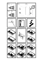

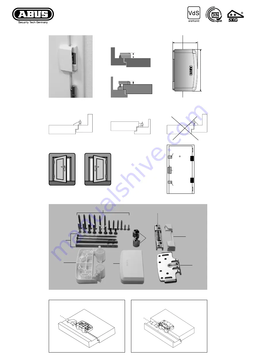
Abb. / fig. / schéma / afb. / ill.
4.1
Abb. / fig. / schéma / afb. / ill.
4.2
Abb. / fig. / schéma / afb. / ill.
1
30,5
108
66
15,5
Abb. / fig. / schéma / afb. / ill.
2
Abb. / fig. / schéma / afb. / ill.
2a
Abb. / fig. / schéma / afb. / ill.
2b
KZS3/HZS3
KLZS/HLZS
TAS
SSB
2200
2300
TAS
4000/9000
4000/9000
Abb. / fig. / schéma / afb. / ill.
3
7
1
4
5
2
6
3
8
D
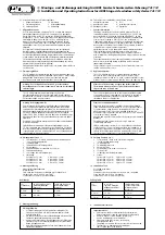
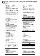
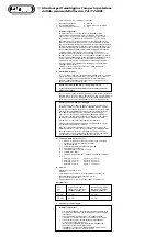
Montage- und Bedienungsanleitung
für ABUS Fenster-Scharnierseiten-Sicherung TAS 112


