background image


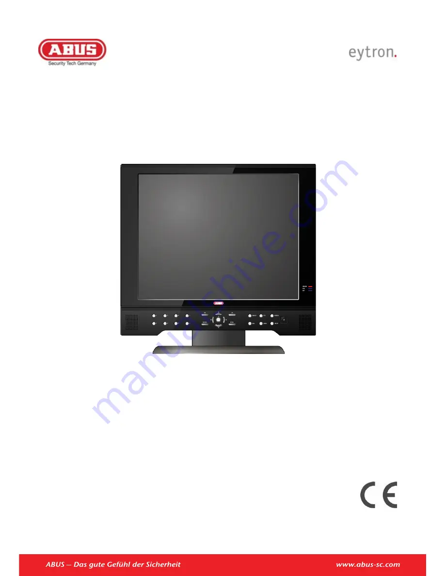
4/8-Channel 19“ Combo DVR 

TVVR25000 / TVVR25010 


User manual 


Version 1.1 


Summary of Contents for TVVR25000

Page 1: ...4 8 Channel 19 Combo DVR TVVR25000 TVVR25010 User manual Version 1 1 ...

Page 2: ...on and operation This should be also noted when this product is passed on to a third party Therefore look after these operating instructions for future reference A list of contents with the corresponding page number can be found in the index All documents can also be found in the internet at www abus sc com ...

Page 3: ...vice overview 3 Device overview Front view Rear view Bottom side view The pictures show TVVR25010 with 8 channels DVR model TVVR25000 is similar See System control page 12 5 6 7 8 9 10 1 2 3 4 11 12 13 14 ...

Page 4: ...Device overview 4 Remote control 16 17 18 19 15 20 21 22 23 24 25 26 27 28 29 30 31 32 33 ...

Page 5: ...0 Putting into operation 10 Children and the device 10 Introduction 11 General information 11 Unpacking the device 11 Scope of delivery 11 System control 12 General 12 Control buttons on the front panel 12 Connectors 12 Remote control 13 Mouse control 13 Keyboard 14 Switching off and locking the device 14 Live view 15 General 15 Menu bar 15 Popup menu 15 Menu 16 SETUP 16 SYSTEM SETUP 16 RECORD SET...

Page 6: ...e on waste electrical and electronic equipment 35 Information on handling batteries 35 Important information on disposing of batteries 35 Information on the European RoHS directive 35 Glossary 36 Overview of specialist terms 36 Internal HDD 38 ...

Page 7: ...2 Connect the audio connections 3 Connect the LAN connection to the network 4 Connect the sensors to the alarm inputs 5 Connect the mouse to the USB port 6 Furthermore you can connect a PC to the DVI input of the device 7 Connect the power supply 8 Switch on the device by pressing the power button on the front side of the device Selecting the input You can use the 19 combo DVR as surveillance and ...

Page 8: ...lid for damages caused by non compliance with these operating instructions We cannot be held liable for resulting damages Warning We cannot be held liable in the event of material or personal damage caused by improper opera tion or non compliance with the safety information All guarantee claims are invalid in such cases Keep this manual in a safe place for future reference If you pass on or sell t...

Page 9: ...that do not conform to the applicable safety standards and do not make alterations to power supply cables or mains cables Installation location operating environ ment x Position the device on a firm level surface and do not place any heavy objects on the device x The device is not designed for operation in rooms subject to high temperatures or moisture e g bath rooms or in excessively dusty rooms ...

Page 10: ...per repairs can expose device users to the risk of fatal injury Accessories x Only connect devices that are suitable for the in tended purpose Otherwise hazardous situations or damage to the device can occur Putting into operation x Observe all safety and operating instructions before putting the device into operation for the first time x Only open the housing to install the HDD Warning When insta...

Page 11: ...the product and operating instructions at any time and without prior warning ABUS Se curity Center GmbH is not liable or responsible for direct or indirect damages resulting from the equipment performance and use of this product No forms of guarantee are accepted for the con tents of this document General information In order to use the device correctly read this user man ual carefully and keep it...

Page 12: ...ed 3 MODE Selects between DVR mode and DVI input PTZ Selects PTZ mode in live display SEARCH Displays the archive menu DISPLAY Selects various display modes in live display and playback ZOOM Selects digital zoom mode in live display SETUP Displays the setup menu 4 Power Turns the system power on off Connectors Note Pay attention to the overview on page 3 Name and function 5 Audio Cinch inputs 6 Vi...

Page 13: ...24 ARCHIVE Displays the archive menu 25 AUDIO Switches between live audio channels Channels 1 4 only Press Audio and select the channel 1 4 26 VOLUME Increase or decrease the volume of a camera during broadcasting live audio 27 NUMBER buttons Use to switch between cameras in live view mode 28 SEARCH Opens the payback search menu 29 ENTER x Press to select an option in a menu x Press to display PIP...

Page 14: ...rrent setting is displayed above the keyboard x To cancel the entry or exit the field press ESC Switching off and locking the device Click on Power in the main menu The overview appears x To switch off the device select Power Off and con firm by entering the password The device is then switched off x Do not press any keys during the shutdown pro cedure 3 To lock the system select Log Off and confi...

Page 15: ...By clicking the icons on the menu bar you can easily ac cess all main menus Furthermore the current date and time network connection HDD usage is displayed User log off and DVR power off System Setup and Record Setup Archiving Search Different viewing modes PTZ control Digital zoom Log file Start Stop panic record Popup menu Press the right mouse button in live view to bring up the popup menu Free...

Page 16: ... RECORD SETUP Recording settings SYSTEM SETUP All non recording specific setting can easily be made here CAMERA CAMERA SETUP TITLE Camera name COVERT When it is set to ON the camera image is not displayed in live display but continues to be recorded AUDIO Determines the audio recording channel COLOR SETUP Brightness contrast tint and color can be adjusted for each individual channel ...

Page 17: ...ered parameters baud rate data bit etc MOTION SENSOR SENSITIVITY Between 1 Lowest and 10 Highest and determines the degree of motion re quired before recording is activated MOTION SENSOR AREA SETUP Choosing this option allows the operator to define which areas of the image are monitored for motion detection Press and hold left button and drag the mouse to mark an area By pressing the right button ...

Page 18: ...ording any channels in D1 resolution 704 x 576 this should be set to ON to prevent judder during playback ALARM POP UP MODE When set to ON an alarm input will cause the associated channel to display in full screen mode ALARM POP UP DWELL Determines how long the full screen popup is displayed after an alarm input is triggered If the alarm condition continues the popup screen is displayed con stantl...

Page 19: ...equence You can determine which channels are displayed and in which sequence SOUND AUDIO LIVE AUDIO When it is set to ON the selected audio channel can be monitored on the AUDIO OUTPUT DEFAULT AUDIO CHANNEL Specify which one of the 4 AUDIO INPUTS is routed to the AUDIO OUTPUT NETWORK AUDIO TRANSMISSION When set to ON live and playback audio is transmitted to a remote PC connection NETWORK AUDIO RE...

Page 20: ...ION S W Version H W Version Video Signal Type Disk Capacity IP Address MAC Address DDNS Domain Name Net Client Port Web Server Port SYSTEM NAME Name of the DVR which is shown in emails F W UPDATE Firmware updates may be re leased periodically to enhance system performance and add ex tra features The operator can up grade the firmware using a USB memory stick Copy the file to a USB stick and insert...

Page 21: ... or USER E MAIL Enter the users email address if email notification is required Max 64 Char acters E MAIL NOTI Enable or disable email notifications for this particular user DELETE Delete the current user USER AUTHORITY Define the different rights for MANAGER and USER SETUP Change settings PTZ Control PTZ cameras SEARCH Enter the SEARCH menu ARCHIVING Enter the ARCHIVING menu REMOTE AGENT Connect ...

Page 22: ...t number that the DVR uses to support remote connection from Inter net Explorer If connected router support UPNP Universal plug and play function port forwarding is automatically setup when pressing AUTO PORT Furthermore the port can be deleted or tested MAX TX SPEED Specifies the maximum bandwidth that the DVR can use during a remote con nection DDNS 1 To use the ABUS DDNS function you must first...

Page 23: ...Menu 23 is used only for E mail test E mail sender TEST E MAIL Enter an e mail address and press TEST to send a test e mail ...

Page 24: ...e en abled or disabled MODE Can be either TRANSPARENT the output is active when the criteria is triggered or LATCHED the output is active for a set period of time after it has been triggered DURATION In LATCHED mode the time that the alarm output remains active after it has been triggered TYPE Can be set to high 0V to 5V when activated or low 5V to 0V when acti vated HDD EVENT Determines whether a...

Page 25: ...zzer MOTION Determines whether motion detection on any of the selected channels will sound the buzzer E MAIL NOTIFICATION Determines the behavior and actions that will send an email to a user NOTIFICATIOM E mail notification can be turned ON or OFF SETUP CHANGE Determines whether a change in the setup sends an email HDD EVENT Determines whether a hard drive event sends an email BOOTING EVENT Deter...

Page 26: ...Once the DVR has reached the limit it will start to overwrite the earliest recorded data OVERWRITE If set to ON the DVR will start to over write the earliest recorded data once the hard drive is full In this case the HDD used percentage shown in the live display will always be 99 When it is set to OFF the DVR will stop re cording when the disk is full FORMAT Click to format all data on the HDD Not...

Page 27: ...r each chan nel can be defined across a 24 hour period in blocks for example between 09 00 and 18 00 or for each individual hour Note that when SCHEDULE MODE is set to WEEKLY each day of the week can also be selected ACTIVATION This section determines at what times the DVR will record and whether it is in continuous recording or motion detection SIZE FPS QUALITY In order to change the recording se...

Page 28: ...gure the recording settings if an alarm input is triggerd Continous recording and alarm recording canbe combined For example the reocrder will record continuously at a low frame rate and then increase to a higher frame rate during an alarm inputis triggered Please refer to CONTINUOUS MOTION setup for details on setting up SIZE FPS QUALITY and ACTIVIATION PANIC RECORDING Here you can configure the ...

Page 29: ...y device FROM Enter a start time TO Enter an end time LOG Select if a log file should be copied to the USB medium QUERY Press to search for data RELEASE Press to release search results RESERVE Press to place the search result to RESERVED DATA MANGEMENT and burn later BURN Press to copy current search result to connected USB medium RESERVED DATA MANGEMENT All reserved video and snapshot files are l...

Page 30: ...clock Channel 1 6 00 9 00 o clock Channel 1 9 00 12 00 o clock Channel 1 12 00 15 00 o clock Channel 1 15 00 18 00 o clock Channel 1 18 00 21 00 o clock Channel 1 21 00 24 00 o clock The user can easily view one camera at different daytimes PLAY Start playback from the selected time In the playback controls there is the option to start immediate backup SEARCH BY EVENT Here you can search the log f...

Page 31: ...ive X control elements must be loaded for the web inter face to be displayed correctly Confirm the download and install the elements Live Mode In Live mode all connected cameras and status are dis played Button Description Different display modes Select next camera Full screen display Select a channel x Start stop live recording x Print the current screen x Create a snapshot of the current screen ...

Page 32: ... cameras Search Mode In the Search mode you can view recordings You can search for recordings by using the time bar or by events Furthermore you can backup recorded data by pressing the button Backup Search Mode In Setup Mode you have access to all settings of the DVR and can change these remotely ...

Page 33: ...ule motion alarm Search modes Event date time Panorama Alarm inputs NO NC 4 8 Relay outputs 1 User levels 5 user levels Network connector RJ45 10 100 Mbit Simultaneously remote connection 4 Network functions Live view search backup setup DDNS NTP PTZ Control PTZ protocols Pelco D Pelco P D MAX Panasonic WV CSR604 Panasonic WV CS850 Alerting Acoustic signal OSD signal Email Audio Audio In 4 x RCA 1...

Page 34: ...space for recording and surveillance depends on the set resolution and frame rate of the recording Continuous recording 1TB HDD Channels Resolution FPS Quality Recording time 4 CIF 25 Highest 48 days 4 2CIF 16 Highest 30 days 4 4CIF 8 Highest 23 days 8 CIF 25 Highest 24 days 8 2CIF 16 Highest 15 days 8 4CIF 8 Highest 11 days ...

Page 35: ...l children Children may put batteries in their mouths and swallow them This can cause serious harm to their health If this happens consult a doctor immedi ately x Do not charge normal batteries heat them up or throw them into naked flames they may explode x Change low batteries in good time x Always change all the batteries at the same time and use batteries of the same type Important Leaky or dam...

Page 36: ...on of websites on the Inter net e g www abus sc de Dual Stream Dual stream is a video transmission method A high resolution recording and lower resolution transmission are made over the network for example The main stream has a 4CIF resolution and the sub stream has a CIF resolution DVR Digital Video Recorder A device used for recording dif ferent video and audio sources analogue digital The data ...

Page 37: ...nsmission or display PIP Picture in Picture Where two signal sources are shown on the screen at the same time The second signal source is stored above the first PPPoE PPP over Ethernet point to point protocol Network transmission method used for establishing a connection over dial up lines Used in ADSL connections for example PROGRESSIVE Method for displaying storing or transmitting moving im ages...

Page 38: ...he device immediately after switching it off To move the device carry out the following steps 1 Wait until OFF has been shown on the display for at least two minutes 2 Remove the mains plug from the socket 3 Move the device x Data on the HDD can be lost in the event of a power failure during operation Use an uninter ruptible power supply UPS x The HDD is very sensitive Improper use or un suitable ...

Page 39: ...ABUS 19 Combo DVR TVVR25000 TVVR25010 Manufacturer ABUS Security Center GmbH Co KG Linker Kreuthweg 5 86444 Affing Germany ...

Reviews: