background image

1

TECHNICAL

 INFORMA

TION  

 INFORMAZIONI TECNICHE

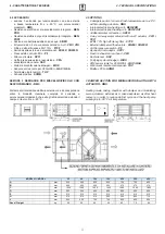
COMPRESSOR DRIVE CFR HPEI 35÷450

Sistema di climatizzazione e deumidificazione con

rinnovo dell’aria e compressore termodinamico

di supporto con ventilatori EC e compressore inverter

Air conditioning and dehumidification system with

air renewal and thermodynamic compressor

support with EC fans and inverter compressor

COMPRESSOR DRIVE 

CFR HPEI

35-60-100-150-230-320-450 

Summary of Contents for 35

Page 1: ...deumidificazione con rinnovo dell aria e compressore termodinamico di supporto con ventilatori EC e compressore inverter Air conditioning and dehumidification system with air renewal and thermodynamic...

Page 2: ...CONTROLS BEFORE START UP 11 MAINTENANCE 11 1 Scheduled maintenance 11 2 Montly checks 11 3 Semiannual checks fans 11 4 Unscheduled maintenance 12 TROUBLESHOOTING 12 1 Troubleshooting guide 12 2 Alarm...

Page 3: ...rle pi evidenti The most important information concerning safety and proper use of themachine are accompanied by some symbols to make them highly visible 2 AVVERTENZE E REGOLE GENERALI 2 WARNINGS AND...

Page 4: ...vo il produttore si riserva di apportare qualsiasi modifica senza preavviso As our Company is constantly involved in the continuous improvement of its production aesthetic characteristics and dimensio...

Page 5: ...a rating plate that describes the following A Mark of the manufacturer B Address of the manufacturer C Unit model D Unit code E Unit serial number F Manufacturing date G Voltage number of phases frequ...

Page 6: ...sportation the installation the use and the maintenance of the heat recovery The user will find everything that is normally useful to know for a correct and safe installation of CFR HPEI air treatment...

Page 7: ...ed polyurethane as heat and sound insulation Filtering sections at both air intakes complete with efficiency cell filters ISO 16890 COARSE 55 G4 EN779 extractable from both lower and side removable pa...

Page 8: ...6 13 8 Temperatura di immissione Supply air temperature C 23 5 23 2 24 1 23 0 21 5 23 0 19 0 PRESTAZIONI IN RAFFRESCAMENTO HEATING 35 60 100 150 230 320 450 Efficienza recupero statico Static recover...

Page 9: ...le technical spaces one of four possible unit configurations can be chosen as shown below air intakes can be easily set so that in line or 90 layout can be matched by moving a side closing panel on jo...

Page 10: ...95 1294 300 210 232 458 115 85 80 90 125 157 1720x1430x520 100 1840 410 1440 1795 1494 400 210 233 703 264 85 80 55 185 232 2020x1630x560 150 1840 500 1440 1795 1494 400 310 233 470 264 85 75 118 228...

Page 11: ...h efficiency filter F7CF External dampers with actuators SR230 SR230R Air filter pressure switch PF Round air duct adaptor SPC1 Fresh exhaust air rain hood CPA Duct silencer SSC Purifying system Bioxi...

Page 12: ...ta coibentata collegabile all unit attraverso idonea canalizzazione essa pu essere impiegata per aiutare la pompa di calore nella modalit riscaldamento o raffreddamento Tramite kit valvola V2O o V3O d...

Page 13: ...mo in abbinata con la serranda ne consente la motorizzazione sono del tipo ON OFF oppure ON OFF con ritorno a molla di sicurezza ed alimentazione 230V Per le dimensioni riferite al passaggio aria si v...

Page 14: ...chiusa da lamiera microstirata sui due lati L onda sonora generata dal ventilatore viene smorzata dall urto con le pareti dei setti con perdite di carico contenute attorno a 40 Pa alla portata nominal...

Page 15: ...ndoor air quality it works when fans are running VISTA DEL POSIZIONAMENTO DEL SISTEMA BIOXIGEN ALL INTERNO DELLA MACCHINA CANALE ARIA MANDATA E RELATIVE DIMENSIONI VIEW OF THE POSITIONING OF THE BIOXI...

Page 16: ...y The re mote display is suitable for wall installation all the informations for wiring and fixing are supplied with the remote display For the main board wiring se e the picture be low Additional boa...

Page 17: ...ati dal trasporto Gli eventuali danni devono essere debitamente comunicati al vettore e specificati nella clausola di riserva riportata nella bolla di accompagnamento When receiving the goods before u...

Page 18: ...are quanto raccomanda il produttore di tali prodotti Prima di mettere in funzione l unit controllare la perfetta integrit dei vari componenti e dell intero impianto Evitare assolutamente di toccare le...

Page 19: ...o in special modo in condizioni di esercizio oltre i limiti operativi indicati a catalogo Posizionare l unit su di una struttura solida adeguata al peso della macchina interporre sempre opportuni sist...

Page 20: ...efer short or long duct connection Compare unit sound level to the required room acoustic comfort and if necessary install suitable sound attenuators 7 6 COLLEGAMENTI IDRAULICI 7 6 WATER CONNECTIONS I...

Page 21: ...linea di alimentazione generale sia sezionata Installare prima l unit principale vedere capitolo 8 poi applicare la guarnizione adesiva fornita a corredo lungo tutto il perimetro i del telaio in allu...

Page 22: ...ator cables arranged on the unit side through the holes fig 5 Connect the cables to the terminal block see the electrical drawing at chapter 8 fig 5 Una volta ancorata la sezione RMS alla struttura po...

Page 23: ...of the pipes must be studied in a way not to create obstacles if the unit coil is extracted Water inlet outlet must be such to allow countercurrent heat exchange follow the indications of the WATER I...

Page 24: ...condo gli schemi elettrici a corredo dell unit e di questo manuale Usare i passacavo presenti sul pannellino frontale per collegare il quadro elettrico interno Before carrying out any service check th...

Page 25: ...25 8 COLLEGAMENTI ELETTRICI 8 ELECTRIC CONNECTIONS pag 26 Manuale di installazione Uso e Manutenzione Installation Use and Maintenance Manual...

Page 26: ...gerant circuit pressure transducers n 2 refrigerant pressure switches Elenco I O I O List Connessione Connection Numero filo Wire number Tipo I O I O Type Segnificato Meaning G G0 G G0 Alimentazione 2...

Page 27: ...ft side of the screen When the menu marked with the letters from A to H appears the required entry can be selected by moving with the arrows Up Down and pushing the button Enter corresponding to the r...

Page 28: ...on which specifies with the first letter the menu in this case A and with 2 digits the number of the page By entering page A02 there are 2 possible options Modo regolazione temperatura che permettere...

Page 29: ...il numero 0 come nella figura sopra si riferisce al fatto che l allarme non riguarda l inverter del compressore Nel caso l allarme registrato riguardi l inverter si vedr in questa riga il codice e la...

Page 30: ...info E Storico Allarmi E Data logger storico allarmi Alarm History F Cambio scheda F Board switch G Assistenza G Service a Cambio lingua change lenguage Cambio lingua Change lenguage G Assistenza G S...

Page 31: ...H Manufacturer c impostazioni costruttore c factory setting Hc08 Impostazioni limitazioni compressore Compressor limitation setting PROSPETTO PARAMETRI MENU ASSISTENZA ASSISTANCE PARAMETER SUMMARY Fun...

Page 32: ...essore Delay from compressor start 0 3600 600 A0 A0 Gfc11 G Assistenza tecnica G Service level f Param Assistenza c Termoregolazione f Service setting c Regulation Isteresi Histeresys 0 10 3 A1 A1 Gfc...

Page 33: ...utton to the left to enter the menu 10 Enter to menu A On Off unit 11 Press YES for the voice Exclusion of local command At this point it s possible to command the input unit see circuit diagram for t...

Page 34: ...za e sottomen e BMS config Valori di default sono indirizzo slave 1 velocit 9600 bps stop bit 2 data bit 8 fisso parit nessuna 9600 N 8 2 L elenco delle variabili ed il relativo significato per la ver...

Page 35: ...point used when CO2 option probe is installaed 18 Set point manuale Freddo Cooling manual setpoint C 26 R W Cooling manual setpoint 19 Set Pont manuale Caldo Heating Manual setpoint C 20 R W Heating m...

Page 36: ...on pressure 20 Stato DI1 DI1 Status R Actual Value of digital input 1 filter switch 21 Stato DI2 DI2 Status R Actual Value of digital input 2 remote on off 22 Stato DI3 DI3 Status R Actual Value of di...

Page 37: ...compressore oppure se la temperatura ambiente scende al di sotto di uno specifico set questa seconda condizione di attivazione abilitata separatamente rispetto alla prima condizione L abilitazione del...

Page 38: ...amente possibile accedere ai filtri presenti a bordo macchina tramite i pannelli asportabili dotati di maniglie collocati sia inferiormente che lateralmente vedi figura l estrazione del filtro avviene...

Page 39: ...stituzione di componenti relativi al circuito frigorifero aeraulico elettrico ed elettronico Tali interventi devono essere demandati esclusivamente a centri di assistenza qualificati ed autorizzati 11...

Page 40: ...ttare servizio di assistenza tecnica Circuito frigorifero scarico o non correttamente carico Contattare servizio di assistenza tecnica 4 Formazione e permanenza di condensa all interno della macchina...

Page 41: ...portata aria in entrambi i flussi che deve essere entro il range di funzionamento dell unit controllare successivamente le pressioni gas del circuito frigorifero Check air flow rate to both flows chec...

Page 42: ...mento aiutano a conservare le risorse naturali e a proteggere la salute umana e l ambiente Iscrizione registro AEE IT16070000009428 I materiali che compongono le unit di recupero calore sono This symb...

Page 43: ...pulsione Exhaust air DX coil BT252EGD026002NO 14 Driver compressore Compressor driver MEINVPS212211200 HPEI 100 1 Ventilatore EC EC motor fan VTDDM0807ECP0400 2 Recuperatore Recovery exchanger PR49003...

Page 44: ...re switch CTPLAF050000FD00 11 Filtro deidratore Freon filter FRFD04S160SMBF00 12 Batteria di mandata Supply air DX coil BT252ED6056005NO 13 Batteria di espulsione Exhaust air DX coil BT252EGM056005NO...

Reviews: