background image


SERVICE  

MANUAL 


MODELS 1250, 1450, 1550, 1650, 1850 


Summary of Contents for 1250

Page 1: ...SERVICE MANUAL MODELS 1250 1450 1550 1650 1850...

Page 2: ......

Page 3: ...Model 1250 Wheel Balancer...

Page 4: ...3 2 CHECKING OF THE RIM DISTANCE GAUGE 3 3 ASSEMBLY OF THE PIEZO MEASURERS 4 4 LOGIC TROUBLE SHOOTING SEQUENCE 5 5 POWER SUPPLY LAYOUT DIAGRAM 6 6 REPLACING THE POWER BOARD 7 7 FUNCTION AND PRECISION...

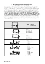
Page 5: ...M 0495 2 GB...

Page 6: ...oard or else modify the board as follows A Replace the capacitor B Replace the transformer 2 CHECKING OF THE RIM DISTANCE GAUGE Check that the ruler used for measuring the DISTANCE of the wheels reads...

Page 7: ...of the coloured wires shown in the drawing 5 Keeping the spindle perfectly aligned tighten the nuts 5 and 6 with a spanner and nuts 3 and 4 by hand by half a turn with the spanner if necessary 6 Re t...

Page 8: ...tage across points 3 4 on the transformer connector correspond to that shown in the layout diagram YES Check that the transformer primary be energized with the mains voltage and that there is not dama...

Page 9: ...M 0495 6 3 GB 5 POWER SUPPLY LAYOUT DIAGRAM 230 V connection...

Page 10: ...M 0495 7 4 GB 6 REPLACING THE POWER BOARD check voltage...

Page 11: ...g the encoder test ALWAYS check that there is a maximum distance of 1 mm between the decal and the encoder card and that the retaining nuts of the encoder card are adequately tightened Use a wheel of...

Page 12: ...lf calibration CHECKING MACHINE OSCILLATION After running autocalibration press STOP to return to the standard measuring frame Without locking the wheel measure the machine oscillation as follows MENU...

Page 13: ...rest point of the edge of the rim The wheel balancing machine automatically corrects the measurement preset by adding 2 x h 6 mm to the measurement Measurement b made with the gauge is generally more...

Page 14: ......

Page 15: ...Model 1450 Wheel Balancer...

Page 16: ...1 TO ENABLE THE GAUGES 4 3 2 CALIBRATION OF THE DISTANCE POTENTIOMETER 5 3 3 CALIBRATION OF THE DIAMETER POTENTIOMETER 5 4 ASSEMBLY OF THE PIEZO MEASURERS 6 5 LOGIC TROUBLE SHOOTING SEQUENCE 7 6 POWER...

Page 17: ...M 0492 2 GB...

Page 18: ...oard or else modify the board as follows A Replace the capacitor B Replace the two transformers 2 CHECKING OF THE RIM DISTANCE GAUGE Check that the ruler used for measuring the DISTANCE of the wheels...

Page 19: ...LE THE GAUGES In the event of faulty operation or replacing a P C board proceed to set the gauges as follows press in sequence and within 5 seconds from when has been pressed Always select ON using bu...

Page 20: ...ecrease by two numbers then retighten the screws to secure the pulley on the shaft Carry out the DISTANCE GAUGE SET UP RIM DISTANCE GAUGE 3 3 CALIBRATION OF THE DIAMETER POTENTIOMETER After CALIBRATIO...

Page 21: ...of the coloured wires shown in the drawing 5 Keeping the spindle perfectly aligned tighten the nuts 5 and 6 with a spanner and nuts 3 and 4 by hand by half a turn with the spanner if necessary 6 Re t...

Page 22: ...1 5 V C A 0 1 5 V C A 7 V C A 0 7 V C A 8 7 6 5 4 3 2 1 12 VDC 12 VDC 3 5 2 4 1 12 VDC 12 VDC 3 5 2 4 1 GB 5 LOGIC TROUBLE SHOOTING SEQUENCE Tests on power 2 relay 2 sonar 1 Transformer output on CN3...

Page 23: ...CA 7 7 0 12 1 CN5 CN4 CN6 CN7 CN10 CN2 CN9 CN1 GB Tests on computer board 1 7 0 7 VCA on CN1 2 Machine SELF TESTS encoder distance gauge diameter gauge sonar width 65 000 in nite should decrease when...

Page 24: ...M 0492 9 ONLY C75 15 15 0 7 0 7 CN7 FS4 2A FS3 2A FS2 2A FS1 2A 7 6 5 4 3 2 1 M EMS SONAR WIDTH SONAR CN2 CN3 CN8 CN1 COMPUTER CN6 GUARD WHEEL M1 1 4 3 2 GB 6 POWER LAYOUT DIAGRAM...

Page 25: ...M 0492 10 ONLY C75 15 15 0 7 0 7 CN7 FS4 2A FS3 2A FS2 2A FS1 2A 7 6 5 4 3 2 1 M EMS SONAR WIDTH SONAR CN2 CN3 CN8 CN1 COMPUTER CN6 GUARD WHEEL M1 1 4 3 2 GB 7 TO REPLACE THE POWER BOARD...

Page 26: ...k that there is a maximum distance of 1 mm between the decal and the encoder card and that the retaining nuts of the encoder card are adequately tightened Use a wheel of average dimensions Press MENU...

Page 27: ...and CALIBRATION OF AUTOMATIC GAUGES DIST between 50 and 1000 by pulling out distance gauge completely DIA between 50 and 1000 by opening diameter gauge wide Calibrate gauges and check accuracy it is...

Page 28: ...spins when t L 10 appears press the buttons to select the desired number in the range 5 999 CHECKING MACHINE CALIBRATION With the wheel perfectly balanced apply 100 g rst on the outside and then on th...

Page 29: ...ects the set measurement by adding 2 x h 6 mm to the measurement The measurement b made with the gauge is normally more accurate even if very similar to the measurement l known by the user The two mea...

Page 30: ......

Page 31: ...Model 1550 Wheel Balancer...

Page 32: ...THE GAUGES 4 3 2 CALIBRATION OF THE DISTANCE POTENTIOMETER 5 3 3 CALIBRATION OF THE DIAMETER POTENTIOMETER 5 3 4 CALIBRATION WIDTH SONAR OPTIONAL 5 4 ASSEMBLY OF THE PIEZO MEASURERS 6 5 TROUBLE SHOOTI...

Page 33: ...M 0493 2 GB...

Page 34: ...voltage proceed as follows 1 Replace the motor 2 Replace the entire power board or else modify the board as follows A Replace the capacitor B Replace the transformers 2 CHECKING OF THE RIM DISTANCE G...

Page 35: ...eed to set the gauges as follows press in sequence and within 5 seconds from when has been pressed Always select ON using buttons con rm select through push buttons depending on the machine type machi...

Page 36: ...wording dIA appears on the left display a number appears on the right display which varies when the gauge is turned and represents a reference for calibrating the potentiometer Remove the diameter gau...

Page 37: ...e position of the coloured wires shown in the drawing 5 Keeping the spindle perfectly aligned tighten the nuts 5 and 6 with a spanner and nuts 3 and 4 by hand by half a turn with the spanner if necess...

Page 38: ...M 0493 7 3 GB 5 TROUBLE SHOOTING SEQUENCE Tests on power board 1 Transformer output on CN1 2 Protection fuses 3 SONAR power supply 4 Computer power supply 5 BRAKING transfer output on CN7...

Page 39: ...1 7 0 7 VCA 12 1 4 GB Tests on computer board 1 7 0 7 VCA on CN1 2 Machine SELF TESTS WHEEL BALANCING MACHINE SELF TEST encoder distance gauge diameter gauge sonar 65 000 in nite should decrease when...

Page 40: ...M 0493 9 5 GB 6 POWER SUPPLY LAYOUT DIAGRAM...

Page 41: ...M 0493 10 6 GB 7 TO REPLACE POWER BOARD...

Page 42: ...there is a maximum distance of 1 mm between the decal and the encoder card and that the retaining nuts of the encoder card are adequately tightened Use a wheel of average dimensions Press MENU The wor...

Page 43: ...completely POTENZIOMETER DIA between 50 and 1000 by opening diameter gauge wide Sonar 1 w monitor Width option From 65000 to 3000 by approaching a target Range 40 11 cm Calibrate gauges and check acc...

Page 44: ...NG MACHINE CALIBRATION With the wheel perfectly balanced apply 100 g rst on the outside and then on the inside The wheel balancer must measure FI 0 FE 100 Weight F E position 6 o clock FI 100 FE 0 Wei...

Page 45: ...ider a typical rim size l given as width by the rim manufacturer differs from the measurement of the distance between the correction planes for the rim thickness and physical dimensions of the counter...

Page 46: ......

Page 47: ...Model 1650 Vibration Control Diagnostic System...

Page 48: ...RATION OF THE DISTANCE POTENTIOMETER 4 4 3 CALIBRATION OF THE DIAMETER POTENTIOMETER 4 4 4 CALIBRATION OF WIDTH AND EMS SONARS OPTIONAL 4 5 ASSEMBLY OF THE PIEZO MEASURERS 5 6 TROUBLE SHOOTING SEQUENC...

Page 49: ...M 0494 2 GB...

Page 50: ...ng to requirements 2 TO CHANGE SUPPLY VOLTAGE See recommended spare parts lists and power layout diagram The machine can run on 115 V 50 60 Hz or 230 V 50 60Hz To change the supply voltage proceed as...

Page 51: ...from the gauge rod after backing off relative set screw Slightly pull out the gauge rod and rest its stop on the machine shaft in external position close to the base Turn the potentiometer shaft unti...

Page 52: ...its in accordance with the position of the coloured wires shown in the drawing 5 Keeping the spindle perfectly aligned tighten the nuts 5 and 6 with a spanner and nuts 3 and 4 by hand by half a turn w...

Page 53: ...SEQUENCE Tests on power board Tests on power board 1 Transformer output on CN1 2 Protection fuses 3 SONAR power supply 4 CHUCK BRAKE power supply 5 Gauge locking power supply 6 Computer power supply...

Page 54: ...er board See gure 4 1 9 0 9 VCA on CN1 2 5 5 on L3 L4 3 Machine SELF TESTS encoder distance gauge diameter gauge sonar width 65 000 in nite should decrease when it re ects EMS sonar 65 000 in nite sho...

Page 55: ...M 0494 8 5 GB 7 POWER SUPPLY LAYOUT DIAGRAM...

Page 56: ...M 0494 9 6 GB 8 TO REPLACE POWER BOARD...

Page 57: ...s Access to the encoder test function From the main panel press the MENU button Press the button 7 Special functions Press the button 3 Machine self test Press the button 2 Encoder Initial test A wind...

Page 58: ...es pect to the reset rising edge 1 Check positioning of the encoder card 2 Clean the encoder decal 3 Move the encoder card up or down Err reset ENCB Detected irregular behaviour of the ENCB falling ed...

Page 59: ...ec Press the START button The wheel balancer runs the number of spins set in automatic cycle and provides the maximum oscillation value 6 Checking machine calibration With the wheel perfectly balanced...

Page 60: ...ble to the serial output see g 9 4 Switch on the machine The words MEMORY LOADER appear on the screen Operations on the PC 5 Connect the other end of the serial cable to the serial output of the PC 6...

Page 61: ...tomatically corrects the measurement preset by adding 2 x h 6 mm to the measurement Measurement b made with the gauge is generally more accurate even if very similar to the measurement l known to the...

Page 62: ......

Page 63: ...Model 1850 Wheel Balancer...

Page 64: ...IAMETER GAUGE ENABLE 4 3 2 CALIBRATION OF THE DISTANCE POTENTIOMETER 4 3 3 CALIBRATION OF THE DIAMETER POTENTIOMETER 5 4 ASSEMBLY OF THE PIEZO MEASURERS 5 5 LOGIC TROUBLE SHOOTING SEQUENCE 6 6 POWER L...

Page 65: ...M 0496 GB 2...

Page 66: ...oard as follows A Replace the capacitor B Replace the transformer C Replace the solenoid group 2 CHECKING OF THE RIM DISTANCE GAUGE Check that the ruler used for measuring the DISTANCE of the wheels r...

Page 67: ...TANCE POTENTIOMETER Remove the weight shelf and re t the tip on the gauge rod Unscrew the lock nuts securing the pulley to the potentiometer shaft From FUNCTION MENU MANAGEMENT SET UP SELF DIAGNOSTICS...

Page 68: ...them proceed as follows 1 Remove the weight shelf 2 Remove nuts 1 and 2 with relative cup springs and washers 3 Back off screws 3 4 6 and 5 then disassemble the various parts 4 Reassemble the various...

Page 69: ...age across points 1 3 and the earth on CN4 correspond to that shown in the layout diagram Check that the transformer primary be energized with the mains voltage and that there is not damage in the wir...

Page 70: ...START STOP 2A 1A 2 1 7 6 5 4 3 2 1 9 0 M POWER BOARD 9 FS1 2A 9Vca 9Vca CN4 FS2 2A MICROSWITCH WHEEL GUARD CN2 COMPUTER BOARD CN1 M 0496 GB 7 6 POWER LAYOUT DIAGRAM...

Page 71: ...START STOP 7 6 5 4 3 2 1 M POWER BOARD FS1 2A FS2 2A MICROSWITCH WHEEL GUARD CN2 COMPUTER BOARD CN1 1 2 1A 2A M 0496 GB 8 7 TO REPLACE THE POWER BOARD Check voltage...

Page 72: ...f the encoder card are adequately tightened Use a wheel of average dimensions Press MENU The word Setup appears ENTER The word Diagn appears MENU STOP MENU Press in sequence in maximum 5 sec The word...

Page 73: ...cy Tolerances DIST 5 mm DIAM CALIBRATION see CALIBRATION Use the same wheel as for gauge calibration Set accurate measures in manual mode if necessary Make self calibration CHECKING MACHINE OSCILLATIO...

Page 74: ...n a ne balanced wheel upside down 180 and detect unbalance rates ERR MAX This check out in particular must be made with a sample wheel whose max unbalance errors due to centering are well known genera...

Page 75: ...ng 2 x h 6 mm to the measurement Measurement b made with the gauge is generally more accurate even if very similar to the measurement l known to the rim user The two measurements differ only by the th...

Page 76: ...SERVICE MANUAL MODELS 1250 1450 1550 1650 1850...

Page 77: ...ptional END OF SELF DIAGNOSTICS CANCELS SELF DIAGNOSTICS IN ANY PHASE The RH display indicates the current position of the wheel with numbers from 0 to 127 Turning the wheel in the direction of rotati...

Page 78: ...e is not correctly calibrated therefore all subsequent measurements will be incorrect until a new self calibration is performed with the correct dimensions Perform a spin under normal conditions Add a...

Page 79: ...alancing system is not used for the time period defined in the relative set up Modify time expressed in minutes CONFIRMATION If the value is set to 0 the screen saver is automatically disenabled The s...

Page 80: ...the error persists contact the Technical Service Department In the event of incorrect input in the rim distance gauge calibration function press to cancel it 6 4 2 Diameter gauge First notch Second n...

Page 81: ...m radial distance from the flange as indicated in the figure The number 256 3 should appear on the left display If not press the button holding the gauge still at 40 mm The number 256 appears on the l...

Page 82: ...5 GB GB sensor and the jaws of the distance gauge in pos 0 as shown in the figure below In the event of incorrect input in the width gauge calibration function press to cancel it 0 gauge first notch D...

Page 83: ...e machine 5 Replace the computer board Err 4 Rotation in opposite direction After pressing START the wheel begins to rotate in the opposite direction anti clockwise 1 Verify the connection of the UP D...

Page 84: ...on the eccentricity measurement sonar correctly before performing the measurement 2 Make sure that the wheel does not stop before completing at least 4 5 revolutions after the rst braking impulse 3 Ve...

Page 85: ...e print function Err 70 Error regarding ADC 16 bit readings 1 Check correct connection cable for distance and diameter gauge CN5 CN4 2 Switch off the machine wait about 30 seconds and switch on again...

Reviews: