background image

A315-53

A315-53G

S E R V I C E  G U I D E

Summary of Contents for A315-53G

Page 1: ...A315 53 A315 53G S E R V I C E G U I D E ...

Page 2: ... Flash Utilities 2 21 BIOS Secure Flash Utilities 2 21 DMITools Utility SOP 2 36 LAN MAC Address Modify SOP 2 55 Crisis Utility SOP 2 57 Chapter 3 Jumper and Connector Locations Mainboard Top View UMA 3 2 Mainboard Top View Discrete 3 3 Mainboard Bottom View UMA 3 4 Mainboard Bottom View Discrete 3 5 USB Board View 3 6 Lid Switch Board View 3 7 Clear CMOS Jumper 3 8 Chapter 4 Troubleshooting Gener...

Page 3: ...er Case Removal 5 27 Lower Case Installation 5 30 Battery Removal 5 32 Battery Installation 5 34 USB Board Removal 5 37 USB Board Installation 5 39 DC IN Cable Removal 5 42 DC IN Cable Installation 5 44 HDD Cable Removal 5 46 HDD Cable Installation 5 47 WLAN Module Removal 5 48 WLAN Module Installation 5 50 SSD Module Removal 5 52 SSD Module Installation 5 53 Fan Module Removal 5 55 Fan Module Ins...

Page 4: ...DP Cable Installation 5 119 WLAN Antenna Aux Removal 5 121 WLAN Antenna Aux Installation 5 123 WLAN Antenna Main Removal 5 125 WLAN Antenna Main Installation 5 126 Chapter 6 FRU Field Replaceable Unit List Exploded Diagram 6 3 Main Assembly 6 3 Upper Cover Assembly 6 5 LCD Assembly 6 6 FRU List 6 8 Screw List 6 19 Chapter 7 Test Compatible Components Microsoft Windows 10 Environment Test 7 2 A315 ...

Page 5: ...s either expressed or implied with respect to the contents hereof and specifically disclaims any warranties of merchantability or fitness for any particular purpose Any Acer Incorporated software described in this manual is sold or licensed as is Should the programs prove defective following their purchase the buyer and not Acer Incorporated its distributor or its dealer assumes the entire cost of...

Page 6: ...s command names option letters and words are shown in constant width bold Variables contained within user input are shown in square brackets Example At the prompt type run file name m Keyboard keys are shown in bold italics Example After entering data press Enter Screen output text that represents information displayed on the system such as menus prompts responses to input and error messages are s...

Page 7: ... guide In such cases contact your regional offices or the responsible personnel channel to provide you with further technical details When ordering FRU parts Check the most up to date information available on your regional web or channel If for whatever reason a part number change is made it may not be noted in this printed service guide For Acer authorized service providers Your Acer office may h...

Page 8: ...onfigurations Hardware Specifications and Configurations 1 2 Features 1 2 Notebook Tour 1 6 Top View 1 6 Left View 1 7 Right View 1 8 Base View 1 9 Touchpad Basics 1 10 Keyboard Basics 1 12 System Block Diagram 1 15 Specifications Table 1 17 ...

Page 9: ...ylake U Intel Kabylake RU System Memory DDR4 1866 2133 SODIMM memory interface design Supported memory size per socket is up to 20GB Supported on board memory is 4GB Display 15 6 WXGA 1366x768 15 6 FHD 1920x1080 15 6 UHD 3840x2160 Reserved Type TN Slim Type 3 2mm IPS Slim Type eDP interface Mercury free environment friendly Graphics UMA GPU nVidia GeForce series 23x23mm N16S GTR 2G or N17S G0 2G V...

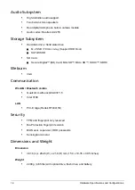
Page 10: ...D Door SATA SSHD SD Card Secure Digital SD Card Mini SD Micro SD SDXC SDHC Webcam VGA Communication WLALN Bluetooth combo Qualcomm Atheros QCA9377 5 Intel 3168 LAN PCI E Giga Reltek RTL8411B Security TPM and fingerprint only reserved Bio Protection fingerprint solution BIOS user supervisor HDD passwords Kensington lock slot Dimensions and Weight Dimension 381 6 L x 262 8 W x 21 6 H mm 15 0 x 10 35...

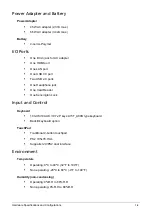
Page 11: ...port Two USB 2 0 ports One Headphone jack One Card Reader One Kensington Lock Input and Control Keyboard 103 US 104 UK 107 JP keys LV5T_A80B type keyboard Backlit keyboard option TouchPad Traditional 2 button touchpad PS2 105x76 7mm Supports I2C PS2 dual interface Environment Temperature Operating 0ºC to 40ºC 32 F to 104 F Non operating 20ºC to 60ºC 4 F to 140 F Humidity non condensing Operating 0...

Page 12: ...1 5 Hardware Specifications and Configurations Warranty One year International Travelers Warranty ITW ...

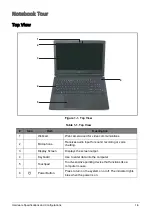
Page 13: ...ommunications 2 Microphone Receives audio input for sound recording or voice chatting 3 Display Screen Displays the screen output 4 Keyboard Use to enter data into the computer 5 Touchpad Touch sensitive pointing device that functions like a computer mouse 6 Power Button Press to turn on the system on or off The indicator lights blue when the power is on 6 1 2 3 4 5 ...

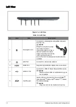
Page 14: ...r Insert the lock into the notch and turn the key to secure the lock Some keyless models are also available 2 LAN Port Connects to a local area network 3 HDMI Port Supports high definition digital video connections 4 USB 3 0 Port Connects to USB 3 0 Super Speed USB device NOTE Devices without USB 3 0 certification may not be compatible 5 Card Reader Insert a memory card such as Secure DigitalTM SD...

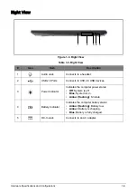
Page 15: ...set 2 USB 2 0 Ports Connects to USB 2 0 USB devices 3 Power Indicator Indicates the computer power status Off System is off Blue System is on Amber flashing S3 state 4 Battery Indicator Indicates the computer battery status Amber flashing Battery low Amber Battery is charging Blue Battery is fully charged 5 DC In Jack Connects to an AC adapter 1 2 3 4 5 ...

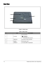
Page 16: ...ns Base View Figure 1 4 Base View Table 1 4 Base View Item Description 1 Air Vents Use for air flow CAUTION Do not cover the air vents 2 RAM Door Covers the memory modules 3 Speaker Emits audio sound 4 HDD Door Covers the HDD compartment 2 1 3 4 ...

Page 17: ...o move the cursor Tapping on the touchpad is the same as clicking the left mouse button 2 Left Button Press the left button to perform selection and execution functions This button is equivalent to the left button on a mouse 3 Right Button Press the right button to perform selection and execution functions This button is equivalent to the right button on a mouse 2 1 3 ...

Page 18: ...e touchpad and your fingers dry and clean Below is a description of basic touchpad operations Table 1 6 Touchpad Operations Function Touchpad Left Button Right Button Execute Tap twice same speed as double clicking a mouse button Quickly click twice Select Tap once Click once Drag Tap twice on the second tap rest your finger on the touchpad and drag the cursor Press and hold then use your finger o...

Page 19: ...s are typed in uppercase 2 Fn Function Key Use with other key combinations to perform special functions 3 Windows Key Press to launch the Start menu When used with other keys provides a variety of functions See Windows Key on page 1 13 4 Application Key Press to open the context menu of the current application This key has the same effect as clicking the right mouse button 1 2 3 4 ...

Page 20: ... F Searches for a file or folder D Shows the desktop L Locks the computer if you are connected to a network domain or switch users if you are not connected to a network domain CTRL F Searches for computers if you are on a network CTRL TAB Moves focus from the Start menu to the Quick Launch toolbar and to the system tray Use the right and left arrow keys to move focus to items on the Quick Launch t...

Page 21: ...eases screen brightness Display Toggle F5 Switches the display output between the display screen external monitor if connected and both Screen Blank F6 Turns the display screen backlight off to save power Press any key to return Touchpad Toggle F7 Turns the touchpad on and off Speaker Toggle F9 Turns the speaker on or off Volume Down F10 Decreases audio volume Volume Up F11 Increases audio volume ...

Page 22: ...1 15 Hardware Specifications and Configurations System Block Diagram Figure 1 7 System Block Diagram UMA ...

Page 23: ...Hardware Specifications and Configurations 1 16 Figure 1 8 System Block Diagram Discrete ...

Page 24: ... 0ºC 40ºC 32ºF 104ºF Operating writing to optical disc 0 C to 40 C 32 F to 104 F Non operating 20ºC 60ºC 4º 140ºF Relative humidity Operating 0 R H to 80 R H Non operating 0 R H to 80 R H Maximum altitude unpressurized Operating NA NA Non operating NA NA Shock Operating 105 G 2 ms half sine Non operating 220 G 2 ms half sine Random vibration Operating 0 60 G zero to peak 5 Hz to 500 Hz 30 minutes ...

Page 25: ...LC255 codec Amplifier Realtek ALC255 build in class D speaker amplifier LAN Card reader Realtek RTL8411B with SD card reader EC ENE KB9022QD Item Specification CPU type Intel Kabylake U porcess 2 2 15W Intel Kabylake RU processor 4 2 15W Intel Kabylake U Platform KBL U2 3e Fuse down PCH LP CPU package BGA1356 Core logic Kabylake U Kabylake2 2 and PCH LP Intel Kabylake RU processor 4 2 15W Intel Ka...

Page 26: ... None 14 3 BGA1356 0 1 5V I5 8250U 1 6G 4 None 14 6 BGA1356 0 1 5V I3 8130U 2 2G 2 None 14 4 BGA1356 0 1 5V I3 7020U 2 3G 2 None 14 3 BGA1356 0 1 5V I3 7020UF RU22 2 3G 2 None 14 3 BGA1356 0 1 5V I3 7020U U22 2 3G 2 None 14 3 BGA1356 0 1 5V I3 7020U U23e fuse down 2 3G 2 None 14 3 BGA1356 0 1 5V I3 7130U 2 7G 2 None 14 3 BGA1356 0 1 5V I3 8130U 2 2G 2 None 14 4 BGA1356 0 1 5V ...

Page 27: ...5 2000 22 50 2300 25 55 2700 28 60 3100 31 65 3500 34 72 3800 37 85 4600 40 90 5300 43 CPU TCC active at 98 C Prochot at 99 C OS shut down at 100 C H W shut down at PH1 92 C Discrete SKU VGA Temp Fan Speed RPM SPL Spec dBA 50 2700 28 55 3100 31 60 3500 34 65 3800 37 80 4600 40 85 5300 43 Prochot at 99 C OS shut down at 100 C ...

Page 28: ...form Memory size 4G DDR4 memory down DIMM socket number x1 DDR4 type socket Supports memory size per socket 2G 4G 8G 16G Supports maximum memory size Total 20GB Supports DIMM type DDR4 SO DIMM Supports DIMM Speed DDR4 1866 2133 Support DIMM voltage 1 2V Supports DIMM package DDR4 SODIMM 260 Pin On Board Memory GB Slot 2 GB Total Memory GB 4 0 4 4 2 6 4 4 8 4 8 12 4 16 20 ...

Page 29: ...DIA N16S GTR or N17S G0 Package FCBGA 595P Interface Internal PCIE x4 Memory 2GB GDDR5 at 1 35V Item Specification BIOS vendor Insyde BIOS Version V1 08 BIOS ROM type SPI BIOS ROM size 8MB Features Insyde code base Flash ROM 8MB Support Acer UI Support multi boot Suspend to RAM S3 Disk S4 Support SMBIOS 2 8 PCI2 1 DMI utility for BIOS serial number configurable asset tag Support PXE Support WinFla...

Page 30: ... CRC Cyclic Redundancy Check function Customizable LEDs Controllable LED Blinking Frequency and Duty Cycle Built in switching regular Built in LDO regulator Supports PCI MSI Message Signaled Interrupt and MSI X Supports LTR Latency Tolerance Reporting and OBFF Optimized Buffer Flush Fill Supports 16 set 128 byte Wake Up Frame pattern ex act matching Supports Microsoft WPD Wake Packet Detection Sup...

Page 31: ...ependent pgdn pgup home end keys Support reverse T cursor keys Factory configurable different languages by OEM customer Item Specification Vendor and model names SEAGATE ST500LT012 SEAGATE ST1000LM035 SEAGATE ST2000LM007 TOSHIBA MQ01ABF050 WDC WD10SPZX 21Z10T0 WDC WD5000LPCX 21VHAT0 Capacity GB 500GB 1TB 2TB Bytes per sector 512 Bytes 512 Bytes 512 Bytes Data heads 2 2 4 2 2 2 Drive Format Disks 1...

Page 32: ...me KINGSTON RBU SNS8180DS3 128GH MICRON MTFDDAV256TBN 1AR1ZABYY HYNIX HFS128G39TND N210A HYNIX HFS256G39TND N210A Lite ON CV3 8D128 Lite On CV3 8D256 Capacity GB 128GB 256Gb Bytes per sector 512 Bytes 512 Bytes Data heads N A N A Drive Format Disks N A N A Spindle speed N A N A Performance Specifications Buffer size DRAM less 512MB 4Gb 4Gb 2Gb 4Gb Interface SATA SATA Fast data transfer rate Mbits ...

Page 33: ...tion pixels 1920 x 1080 FHD 1366 x 768 HD Pixel Pitch mm 0 17925 mm x 0 17925 mm FHD 0 252 mm x 0 252 mm HD Typical White Luminance cd m2 also called Brightness 220 cd m2 Contrast Ratio Slim eDP FHD TN B156HTN03 8 N156HGA EAB 300 400 400 500 Slim eDP HD TN B156XTN07 1 NT156WHM N42 NT156WHM N32 N156BGA EB2 350 500 TBD 400 TBD 500 400 600 Response Time Optical Rise Time Fall Time msec Slim eDP FHD T...

Page 34: ...TN B156HTN03 8 N156HGA EAB 360g 360g Slim eDP HD TN B156XTN07 1 NT156WHM N42 NT156WHM N32 N156BGA EB2 380g 370g 370g 360g Physical Size mm 359 5 x 223 8 mm Electrical Interface eDP 1 2 Viewing Angle degree Horizontal Right CR 10 Left Vertical Upper CR 10 Lower Slim eDP FHD TN B156HTN03 8 N156HGA EAB 45 45 15 35 45 45 20 45 Slim eDP HD TN B156XTN07 1 NT156WHM N42 NT156WHM N32 N156BGA EB2 45 45 15 3...

Page 35: ... Windows Direct3D 2015 Direct3D 11 2 Direct3D 11 1 Direct3D 9 Direct3D 10 Direct2D OpenGL 5 0 OpenCL 2 1 OpenCL 2 0 OpenCL 1 2 Hardware Accelerated Video Decode Direct3D 9 Video API DXVA2 Direct3D11 Video API Intel Media SDK MFT Media Foundation Transform filters Supports full HW accelerated video decoding for AVC VC1 MPEG2 HEVC VP8 JPEG Hardware Accelerated Video Encode Intel Media SDK MFT Media ...

Page 36: ...ectX 11 2 support OpenGL 4 4 or later support NVIDIA PhysX CUDA VRAM Chipset Hynix Samsung Micron Memory Size 2GB Interface GDDR5 Item Specification Graphics Controller Chip NVIDIA N17S G0 Supports PCI Express 3 0 Interface NVIDIA Optimus technology DirectX 11 2 support OpenGL 4 4 or later support NVIDIA PhysX CUDA VRAM Chipset Micron Hynix Memory Size 2GB Interface GDDR5 ...

Page 37: ...X 1024x768p 60Hz X V X X X 1152x864p 60Hz X V X X X 1280x600 60Hz X V X X X 1280x720 60Hz X V X X X 1280x768 60Hz X V X X X 1280x800 60Hz X V X X X 1280x960 60Hz X V X X X 1280x10240 60Hz X V X X X 1360x768 60Hz X V X X X 1366x768 60Hz X V X X X 1400x1050 60Hz X V X X X 1440x900 60Hz X V X X X 1600x900 60Hz X V X X X 1680x1050 60Hz X V X X X 1920x1080 60Hz X V X X X Legend V Supported X Not suppor...

Page 38: ...B XSRK ETB Supported protocol List only supported protocols from Acer specs A2DP AVCTP AVRCP BIP BPP DUN Fax FTP GAVDP HCRP Headset Hands Free HID OPP PAN SDAP Serial SYNC Item Specification Chipset Intel 3168 Data throughput Wifi 1TX 1RX transmission rate can up to 150Mbps in 802 11n and 433Mbps in 802 11ac BT TX 1 2Mbits sec BT RX 1 2Mbits sec Protocol 802 11a 802 11b 802 11g 802 11n 802 11ac Bl...

Page 39: ...mm Atheros NFA435A Intel 3168 Features Mini USB module with built in antenna Bluetooth 4 0 Item Specification Vendor and Model 6SF009N2 CNFG02321004970LH 1YHJZZZ000 Type VGA Item Specification Number supported x2 Features One for WiFi half card One for SSD full or half card Item Specification Features N A Item Specification Audio Controller Audio Codec Realtek ALC255 CG ...

Page 40: ...resolution VSR Variable Sampling Rate Internal microphone Yes Internal speaker quantity Yes 2W speakers x2 Item Specification Vendor Model name Panasonic AC14B3K LG AC14B8K Battery Type Li ion Li Ion Pack capacity 3220 mAh 3220 mAh Number of battery cell 4 4 Package configuration 4S1P 4S1P Item Specification USB compliance level USB2 0 USB3 0 Protocol xHCI Number of USB port s 3 Location One on th...

Page 41: ...505 HV 2560x1440 60 T272HUL 2560x1440 60 B326HUL 2560x1080 60 B296CL 3840x2160 30 S277HK 3840x2160 30 B326HK Item Specification Input rating 45W 65W Maximum input AC current Input current will less than 1 2Amps at input voltage 90Vac 47Hz and maximum load condition 1 5A Max at 100Vac input voltage Inrush current 264Vac No damage Meet fuse and bridge I2 t de rating No damage Meet fuse and bridge I2...

Page 42: ...wer Down VGA Suspend PCMCIA Suspend Audio Power Down Hard Disk Power Down Super I O Low Power mode Also called Hibernation Mode System saves all system states and data onto the disc prior to power off the whole system Item Specification Chipset Realtek RTL8411B Package 48 PIN QFN Maximum supported size Support SD Support SDXC Support SDHC Type Model Test Result SD Sand Disk 2G Class 2 Pass SD Pana...

Page 43: ...System off Amber color blinking S3 state HDD access state N A Wireless state N A Power button backlight N A Battery state Charging Amber solid on Battery charging with AC Blue color solid on Battery full Amber blinking Battery abnormal stop charge or battery in low power state Discharging Amber and blinking Battery in critical low state Amber color off Discharging state ...

Page 44: ...16 Boot Tab Windows 7 2 16 Boot Tab Windows 10 2 17 Exit Tab 2 19 Boot Manager 2 20 Flash Utilities 2 21 BIOS Secure Flash Utilities 2 21 Shell Secure Flash Utility SOP For Service BIOS 2 22 Windows Secure Flash Utility SOP 2 26 Windows Secure Flash Utility SOP For Service BIOS 2 31 DMITools Utility SOP 2 36 Using DMITools x64 2 36 Using DMITools x86 2 43 Using DMITools DOS 2 50 LAN MAC Address Mo...

Page 45: ...To navigate through the menus options perform the following To choose a menu use the left and right arrow keys To choose an item use the up and down arrow keys To change the value of a parameter press F5 or F6 A plus sign indicates the item has sub items Press Enter to expand this item Press Esc while you are in any of the menu options to go to the Exit menu In any menu you can load default settin...

Page 46: ... HDD Model Name HFS256G39TND N210A This item show the model name of HDD installed The hard disk mode name is automatically detected by the system If there is no hard disk present or unknown type None should be shown on this field InsydeH20 Setup Utility Rev 5 0 F1 Help Select Item F5 F6 Change Values F9 Setup Defaults Esc Exit Select Menu Enter Select Sub Menu F10 Save andExit CPU info Intel R Cor...

Page 47: ...et Tag Number 22 characters minimum Should be same with SMBIOS Type 3 Offset 08h Product Name Acer Brand for example Aspire Aspire XXXX TravelMate TravelMate XXXX Aspire One Aspire One XXX Iconia ICONIA XXXX N A XXXX Gateway Brand for example N A XXXX Packard Bell Brand for example EasyNote EasyNote XXXX N A XXXX Should be same with SMBIOS Type 1 Offset 05h Product Name is defined by project POR T...

Page 48: ...ickly select the boot device Modification to the boot device order apply only for the current session The next time your computer is rebooted it will use again the boot device sequence as set in the BIOS Setup Utility Boot Boot priority order The default value is Disabled InsydeH20 Setup Utility Rev 5 0 F1 Help Select Item F5 F6 Change Values F9 Setup Defaults Esc Exit Select Menu Enter Select Sub...

Page 49: ... resume from S3 state by opening the lid This option is only visible and functions on nonconnected standby supported systems The default value depends on the project definition D2D Recovery Enabled Disabled This function enables disables Acer disc to disc Recovery To do Acer disc to disc system recovery press Alt F10 key during POST GPT Partition Recovery None Save Restore None Do nothing Save Cho...

Page 50: ...e function The default value is Enabled VTD Enabled Disabled This is Intel VTD function switch Display when platform support the function The default value is Enabled SATA Configuration Enter to configure SATA Port InsydeH20 Setup Utility Rev 5 0 F1 Help Select Item F5 F6 Change Values F9 Setup Defaults Esc Exit Select Menu Enter Select Sub Menu F10 Save andExit Intel VTX Enabled Intel VTD Enabled...

Page 51: ...ssword is not set F1 Help Select Item F5 F6 Change Values F9 Setup Defaults Esc Exit Select Menu Enter Select Sub Menu F10 Save andExit InsydeH20 Setup Utility Rev 5 0 Supervisor Password Is Clear User Password Is Clear HDD0 Password Is Clear HDD1 Password Is Clear Set Supervisor Password Enter Set User Password Enter Set HDD0 Password Enter Set HDD1 Password Enter Password on Boot Disabled Secure...

Page 52: ...he value is Clear Frozen If HDD status is frozen Set HDD Password is set Clear User Password is not set For NVMe SSD that does not support HDD password BIOS must display HDDx NVMe SSD does not support HDD password Set Supervisor Password Enter Please refer to the next page Product Information Example Remark ...

Page 53: ...the following dialog box appears 2 Type the current password in the Enter Current Password field and press Enter 3 Type the new password in the Enter New Password field and press Enter 4 Retype the new password in the Confirm New Password field 5 Press Enter If the passwords match the Setup Notice dialog box appears If the current password entered does not match the actual current password press E...

Page 54: ...ture is available to the user if the HDD password is set Password can be added to the HDD usage only when the HDD password is set If the system has more than 1 HDD listed items in Security Menu are as follows Set HDD0 Password Set HDD1 Password Password on Boot Enabled Disabled Defines whether a password is required or not when the events defined in this group take place By default the value is Di...

Page 55: ... 2 5 Select UEFI File Location 2 Use the and keys to select a location then press Enter until you find the file which will be added to trusted file database Figure 2 6 Select UEFI File 3 Select the efi file to execute only efi files can be added to the signature database 4 Enter Boot Description of this file Select Yes to add the signature database and return to the security section Boot descripti...

Page 56: ...eed 12 characters The following characters may be used in a password IMPORTANT Use care when typing a password Characters do not appear on the screen 3 Retype the password in the Confirm New Password field 4 Press Enter The Setup Notice dialog box appears Figure 2 9 Setup Notice 5 Press Enter to complete the password setting After setting the supervisor password the computer sets the Supervisor Pa...

Page 57: ...nd HDD passwords 1 Use the and keys to highlight the Set Supervisor Password parameter and press Enter The Set Supervisor Password dialog box appears Figure 2 10 Set Supervisor Password 2 Type the current password in the Enter Current Password field and press Enter 3 Type the new password in the Enter New Password field and press Enter 4 Retype the new password in the Confirm New Password field 5 ...

Page 58: ...t Supervisor Password parameter and press Enter The Set Supervisor Password dialog box appears Figure 2 12 Set Supervisor Password 2 Type the current password in the Enter Current Password field and press Enter 3 Press Enter twice without typing anything in the Enter New Password and Confirm New Password fields The Setup Notice dialog box appears Figure 2 13 Setup Notice 4 Press Enter to complete ...

Page 59: ... Figure 2 14 BIOS Boot Windows 7 F1 Help Select Item F5 F6 Change Values F9 Setup Defaults Esc Exit Select Menu Enter Select Sub Menu F10 Save andExit InsydeH20 Setup Utility Rev 5 0 Boot Mode Legacy Boot priority order 1 HDD0 HFS512G39TND N210A 2 HDD1 TOSHIBA MQ01ABD100 3 USB FDD 4 Network Boot Realtek PXE B03 D00 5 USB HDD 6 USB CDROM Information Main Advanced Security Boot Exit Item Specific He...

Page 60: ... the user makes modifications to the Boot Mode then the user is prompted to confirm the action as well as informed that the boot device list won t be refreshed until the next BIOS Setup Utility entry and the modification to the Boot Mode will not take effect until the next boot After user flashes BIOS or loads Setup Defaults Boot Mode should return to the factory default values F1 Help Select Item...

Page 61: ...ould only be modified by following actions 1 Supervisor password had been set When BIOS Load Setup Defaults is executed if default Boot Mode is UEFI Secure Boot will reset to Enabled on the contrary if default Boot Mode is Legacy Secure Boot will be disable and hid in Boot Menu When user change Boot mode from Legacy to UEFI Secure Boot will be set to Enabled and shown on Boot Menu Boot Priority Or...

Page 62: ...tility Exit Discarding Changes Exit the BIOS utility without saving the changes to the system Load Setup Defaults Load the default values of all setup items F1 Help Select Item F5 F6 Change Values F9 Setup Defaults Esc Exit Select Menu Enter Select Sub Menu F10 Save andExit InsydeH20 Setup Utility Rev 5 0 Exit Saving Changes Exit Discarding Changes Load Setup Defaults Information Main Advanced Sec...

Page 63: ...indows 10 on page 2 5 Perform the following to use the F12 Boot menu 1 Start the computer 2 When prompted press F12 during POST The Boot Manager screen appears Figure 2 17 Boot Manager Screen 3 Use the and keys to highlight a boot device 4 Press Enter to select and continue with the boot procedure Boot Manager Boot Option Menu 1 Network Boot Realtek PXE B01 D00 2 HDD XXXXXX 3 ATAPI CDROM XXXXXX ɥa...

Page 64: ...ell Secure Flash Utility see Shell Secure Flash Utility SOP For Service BIOS on page 2 22 Windows Secure Flash Utility see Windows Secure Flash Utility SOP on page 2 26 Windows Secure Flash Utility for service see Windows Secure Flash Utility SOP For Service BIOS on page 2 31 NOTE If a Crisis Recovery Disc is not available create one before BIOS Flash utility is used See Creating a USB Flash Crisi...

Page 65: ...nter the BIOS Setup Menu In the Boot menu ensure the Boot Mode is UEFI Then set the USB HDD as the first boot device in Boot priority order Figure 2 19 Configure Boot Parameters 26B9 6B6 B 7 SH LS UFKLYH 26B9 6B6KHOOB 6KHOO 9 6 HIL RRW FAT32 format USB HDD Copy Unzip RRW HIL InsydeH20 Setup Utility Rev 5 0 Information Main Security Boot Exit Boot Mode UEFI Secure Boot Enabled Boot priority order 1...

Page 66: ...ath use cd shell command Figure 2 20 Navigating the Folder 5 Execute the file C5V01100S efi to unlock Intel ME after what the system will automatically reboot Figure 2 21 Unlocking Intel ME EFI Shell version 2 40 21793 40 Current running mode 1 1 2 Device mapping table fs0 HardDisk Alias hd27a0a1 blk0 PciRoot 0x0 Pci 0x13 0x0 Sata 0x0 0x0 0x0 HD 1 GPT 96CBFE01 4E78 fs1 Removable HardDisk Alias hd2...

Page 67: ...ent BIOS version V1 XX _______________________New_____BIOS version V1 XX _______________________Please do not remove the AC power _______________________Please do not remove the AC power Insyde H2OFFT Flash Fireware Tool Version 1 00 51 00 Copyright 2016 Insyde Software Corp All Rights Reserved Loading New BIOS Image File Done Loading New EC Image File Done _____________ __Current BIOS Model name ...

Page 68: ...r Update BIOS Failed Fs1 _ Warning NO AC Connected This process requires AC power and a charged battery to avoid an accidental power off during an update _______________________Please do not remove the AC power Insyde H2OFFT Flash Firmware Tool Version 1 3u Copyright C 2016 Insyde Software Corp All Rights Reserved Error Update BIOS Failed Fs1 _ Warning NO Battery Connected This process requires AC...

Page 69: ...tents of the folder to your computer NOTE In the example below the file is unzip and saved in C location Figure 2 27 Unzip and Copy BIOS ROM Package 2 Click the Windows key shortcut WINKEY X on the keyboard to open the Quick Link menu then choose Command Prompt Admin Figure 2 28 Open Command Prompt 26B9 B 7 SH LS UFKLYH Root Copy Unzip C5V0100 exe 7z Setup SFX Igor Pavlov Microsoft Windows Version...

Page 70: ...hange to the path where C5V01100 exe is saved in step 1 i e C in this case with Command Prompt window Figure 2 30 Change the Directory 5 Execute the C5V01100 exe file to prepare for flashing BIOS and EC firmware The system will automatically reboot Figure 2 31 Execute the C5V01100 exe Microsoft Windows Version 10 0 10586 c 2015 Microsoft Corporation All rights reserved C Windows system32 CD C C C5...

Page 71: ...rs check if the AC is properly plugged in Figure 2 32 AC Detect Error CAUTION If the warning message below is displayed make sure the battery is not disconnected from the system Figure 2 33 Battery Disconnected CAUTION If the warning message below is displayed make sure the battery power is above 25 Figure 2 34 Battery Power is Low ...

Page 72: ...ing New BIOS Image File Done Loading New EC Image File Done _____________ __Current BIOS Model name C5V01 ______________ _New_____BIOS Model name C5V01 _______________ Current System BIOS version V1 XX _______________________Please do not remove the AC power Insyde H2OFFT Flash Fireware Tool Version 1 00 55 00 Copyright 2016 Insyde Software Corp All Rights Reserved Loading New BIOS Image File Done...

Page 73: ...Flash Fireware Tool Version 1 00 55 00 Copyright 2016 Insyde Software Corp All Rights Reserved Loading New BIOS Image File Done Loading New EC Image File Done _____________ __Current BIOS Model name C5V01 ______________ _New_____BIOS Model name C5V01 _______________ Current System BIOS version V1 XX _______________ New_____System BIOS version V1 XX 100 59sec _______________ Start EC Update ...

Page 74: ... package BIOS_V1 xxS_W10X86X64 zip V1 xx Version 1 xx and copy the contents of the folder to your computer NOTE In the example below the file is unzip and saved in C location Figure 2 38 Unzip and Copy BIOS ROM Package 2 Click the Windows key shortcut WINKEY X on the keyboard to open the Quick Link menu then choose Command Prompt Admin 26B9 6B 7 SH LS UFKLYH 26B9 6B LQ 520 9 6 H H 520 Root Copy Un...

Page 75: ...r with Command Prompt window Figure 2 40 Change the Directory 5 Execute the C5V01100S exe file to prepare for flashing BIOS and EC firmware The system will automatically reboot Figure 2 41 Execute the C5V01100S exe Microsoft Windows Version 10 0 10586 c 2015 Microsoft Corporation All rights reserved C Windows system32 CD C cd BIOS_V1 00S_W10X86X64 Win C BIOS_V1 00S_W10X86X64 Win _ C BIOS_V1 00S_DO...

Page 76: ...rs check if the AC is properly plugged in Figure 2 42 AC Detect Error CAUTION If the warning message below is displayed make sure the battery is not disconnected from the system Figure 2 43 Battery Disconnected CAUTION If the warning message below is displayed make sure the battery power is above 25 Figure 2 44 Battery Power is Low ...

Page 77: ...All Rights Reserved Loading New BIOS Image File Done Loading New EC Image File Done __Current BIOS Model name C5V01 _New_____BIOS Model name C5V01 Current System BIOS version V1 XX _____ Requires AC power to avoid an accidental power off Insyde H2OFFT Flash Fireware Tool Version 1 00 55 00 Copyright 2016 Insyde Software Corp All Rights Reserved Loading New BIOS Image File Done Loading New EC Image...

Page 78: ...de H2OFFT Flash Fireware Tool Version 1 00 55 00 Copyright 2016 Insyde Software Corp All Rights Reserved Loading New BIOS Image File Done Loading New EC Image File Done __Current BIOS Model name C5V01 _New_____BIOS Model name C5V01 Current System BIOS version V1 XX New Start EC Update 100 59sec _____System BIOS version V1 XX ...

Page 79: ...All rights reserved USAGE DMITOOLSx64 Rm Rp Rfgsn Rmbsn RUUID Rasset RLM Wm Wp Wfgsn Wmbsn GWUUID WUUID Wasset WLM STRING Rm Read Manufacturer Name Wm Write Manufacturer Name to EEPROM Max 16 characters Rp Read Product Name Wp Write Product Name to EEPROM Max 25 characters Rfgsn Read F G Serial Number Wfgsn Write F G Serial Number to EEPROM Max 22 characters Rmbsn Read M B Serial Number Wmbsn Writ...

Page 80: ...DMITOOLSx64 exe to display the usage options help The following examples show the commands and the corresponding output information 1 Read Manufacturer Name from Memory Instruction DMITOOLSx64 Rm Figure 2 50 Read Manufacture Name Copy COMPAL ELECTRONICS INC DMITOOLSx64 DMITOOLSx64 exe C DMITOOLSx64 Rm COMPAL ELECTRONICS INC V3 0 0 7 Author STD SID TEAM WARNING THIS PROGRAM IS FOR INTERNAL USE ONLY...

Page 81: ...SID TEAM WARNING THIS PROGRAM IS FOR INTERNAL USE ONLY Copyright c 2012 COMPAL ELECTRONICS INC All rights reserved Product Name xxxx xx xxx C DMITOOLSx64 Rfgsn COMPAL ELECTRONICS INC V3 0 0 7 Author STD SID TEAM WARNING THIS PROGRAM IS FOR INTERNAL USE ONLY Copyright c 2012 COMPAL ELECTRONICS INC All rights reserved Serial Number 01234567890123456789 C DMITOOLSx64 Rmbsn COMPAL ELECTRONICS INC V3 0...

Page 82: ...S PROGRAM IS FOR INTERNAL USE ONLY Copyright c 2012 COMPAL ELECTRONICS INC All rights reserved UUID String B57428EB 4CB2 11E1 BE32 002007011606 C DMITOOLSx64 Rasset COMPAL ELECTRONICS INC V3 0 0 7 Author STD SID TEAM WARNING THIS PROGRAM IS FOR INTERNAL USE ONLY Copyright c 2012 COMPAL ELECTRONICS INC All rights reserved Asset Tag String Acer Asset TagD7 DC C DMITOOLSx64 RLM COMPAL ELECTRONICS INC...

Page 83: ...ght c 2012 COMPAL ELECTRONICS INC All rights reserved Waiting Successful Please restart system to make this new DMI data effective C DMITOOLSx64 Wp xxxx xx xxx COMPAL ELECTRONICS INC V3 0 0 7 Author STD SID TEAM WARNING THIS PROGRAM IS FOR INTERNAL USE ONLY Copyright c 2012 COMPAL ELECTRONICS INC All rights reserved Waiting Successful Please restart system to make this new DMI data effective C DMI...

Page 84: ...USE ONLY Copyright c 2012 COMPAL ELECTRONICS INC All rights reserved Waiting Successful Please restart system to make this new DMI data effective C DMITOOLSx64 GWUUID COMPAL ELECTRONICS INC V3 0 0 7 Author STD SID TEAM WARNING THIS PROGRAM IS FOR INTERNAL USE ONLY Copyright c 2012 COMPAL ELECTRONICS INC All rights reserved Waiting Write UUID 39643236 6134 6231 6232 Successful Please restart system...

Page 85: ...em to make this new DMI data effective C DMITOOLSx64 Wlm ERROR The syntax of the command is incorrect Parameter is lack case ERROR The input parameter is lack Over parameters case ERROR The input parameter is too much Syntax is wrong case ERROR The syntax of the command is incorrect Write command with String which length is too long case ERROR The string length is invalid Write UUID and its length...

Page 86: ...Write Manufacturer Name to EEPROM Max 16 characters Rp Read Product Name Wp Write Product Name to EEPROM Max 25 characters Rfgsn Read F G Serial Number Wfgsn Write F G Serial Number to EEPROM Max 22 characters Rmbsn Read M B Serial Number Wmbsn Write M B Serial Number to EEPROM Max 32 characters RUUID Read UUID GWUUID Generate UUID and Write Ignore String WUUID Write UUID to EEPROM Max 20 Hex numb...

Page 87: ...e DMITOOLSx86 exe to display the usage options help The following examples show the commands and the corresponding output information 1 Read Manufacturer Name from Memory Instruction DMITOOLSx86 Rm Figure 2 67 Read Manufacture Name Copy COMPAL ELECTRONICS INC DMITOOLS DMITOOLSx86 exe C DMITOOLSx86 Rm COMPAL ELECTRONICS INC V2 0 0 7 Author STD SID TEAM WARNING THIS PROGRAM IS FOR INTERNAL USE ONLY ...

Page 88: ...SID TEAM WARNING THIS PROGRAM IS FOR INTERNAL USE ONLY Copyright c 2012 COMPAL ELECTRONICS INC All rights reserved Product Name xxxx xx xxx C DMITOOLSx86 Rfgsn COMPAL ELECTRONICS INC V2 0 0 7 Author STD SID TEAM WARNING THIS PROGRAM IS FOR INTERNAL USE ONLY Copyright c 2012 COMPAL ELECTRONICS INC All rights reserved Serial Number 01234567890123456789 C DMITOOLSx86 Rmbsn COMPAL ELECTRONICS INC V2 0...

Page 89: ...HIS PROGRAM IS FOR INTERNAL USE ONLY Copyright c 2012 COMPAL ELECTRONICS INC All rights reserved UUID String B57428EB 4CB2 11E1 BE32 002007011606 C DMITOOLSx86 Rasset COMPAL ELECTRONICS INC V2 0 0 7 Author STD SID TEAM WARNING THIS PROGRAM IS FOR INTERNAL USE ONLY Copyright c 2012 COMPAL ELECTRONICS INC All rights reserved Asset Tag String Acer Asset TagD7 DC C DMITOOLSx86 RLM COMPAL ELECTRONICS I...

Page 90: ...ght c 2012 COMPAL ELECTRONICS INC All rights reserved Waiting Successful Please restart system to make this new DMI data effective C DMITOOLSx86 Wp xxxx xx xxx COMPAL ELECTRONICS INC V2 0 0 7 Author STD SID TEAM WARNING THIS PROGRAM IS FOR INTERNAL USE ONLY Copyright c 2012 COMPAL ELECTRONICS INC All rights reserved Waiting Successful Please restart system to make this new DMI data effective C DMI...

Page 91: ...USE ONLY Copyright c 2012 COMPAL ELECTRONICS INC All rights reserved Waiting Successful Please restart system to make this new DMI data effective C DMITOOLSx86 GWUUID COMPAL ELECTRONICS INC V2 0 0 7 Author STD SID TEAM WARNING THIS PROGRAM IS FOR INTERNAL USE ONLY Copyright c 2012 COMPAL ELECTRONICS INC All rights reserved Waiting Write UUID 39643236 6134 6231 6232 Successful Please restart system...

Page 92: ...em to make this new DMI data effective C DMITOOLSx86 Wlm ERROR The syntax of the command is incorrect Parameter is lack case ERROR The input parameter is lack Over parameters case ERROR The input parameter is too much Syntax is wrong case ERROR The syntax of the command is incorrect Write command with String which length is too long case ERROR The string length is invalid Write UUID and its length...

Page 93: ...Manufacturer Name to EEPROM Max 16 characters Rp Read Product Name Wp Write Product Name to EEPROM Max 25 characters Rfgsn Read F G Serial Number Wfgsn Write F G Serial Number to EEPROM Max 22 characters Rmbsn Read M B Serial Number Wmbsn Write M B Serial Number to EEPROM Max 32 characters RUUID Read UUID GWUUID Generate UUID and Write Ignore String WUUID Write UUID to EEPROM Max 20 Hex number Ras...

Page 94: ...ion DMITOOLS Rm Figure 2 84 Read Manufacture Name 2 Read Product Name from Memory Instruction DMITOOLS Rp Figure 2 85 Read Product Name 3 Read Serial Number from Memory Instruction DMITOOLS Rfgsn Figure 2 86 Read Serial Number 4 Read M B Serial Number from Memory Instruction DMITOOLS Rmbsn Figure 2 87 Read M B Serial Number C DMITOOLS Rm Manufacturer Acer C DMITOOLS Rp Product Name xxxx xx xxx C D...

Page 95: ...tion DMITOOLS Wm Acer Figure 2 91 Write Manufacturer Name 9 Write Product Name to EEPROM Instruction DMITOOLS Wp xxxx xx xxx Figure 2 92 Write Product Name C DMITOOLS RUUID UUID String B57428EB 4CB2 11E1 BE32 002007011606 C DMITOOLS Rasset Asset Tag String Acer Asset TagD7 DC C DMITOOLS RLM LAN MAC B8 88 E3 42 6F BF C DMITOOLS Wm Acer Waiting Successful Please restart system to make this new DMI d...

Page 96: ...UID 14 Write Asset Tag to EEPROM Instruction DMITOOLS Wasset Acer Asstag Figure 2 97 Write Asset Tag C DMITOOLS Wfgsn 01234567890123456789 Waiting Successful Please restart system to make this new DMI data effective C DMITOOLS Wmbsn 01234567890123456789 Waiting Successful Please restart system to make this new DMI data effective C DMITOOLS GWUUID Waiting Write UUID 39643236 6134 6231 6232 Successf...

Page 97: ...After writing items 8 15 restart the system to get the latest DMI data If using the write command enter the correct command string Otherwise it will display a syntax error Figure 2 99 Syntax error C DMITOOLS Wlm B888E3426FBF Waiting Successful Please restart system to make this new DMI data effective C DMITOOLS Wlm ERROR The syntax of the command is incorrect ...

Page 98: ...Find and execute DisableUAC reg Click Yes and OK Then restart your computer Figure 2 100 Execute DisableUAC reg 3 After restart find and execute WINPG64 BAT It will automatically update your MAC address Then press any key to check if the MAC address has already been updated Figure 2 101 Execute WINPG64 BAT ...

Page 99: ...AC address find WINPG64 BAT Right click your mouse on the file and select Edit to edit the file Add RTNicPgW64 exe efuse nodeid MAC as shown in the below illustration Then save the file and repeat step 3 Figure 2 102 Add RTNicPgW64 exe efuse nodeid MAC ...

Page 100: ...ly after updating BIOS i e a black screen appears without a POST logo etc Creating a USB Flash Crisis Disk To create a Crisis USB flash disk perform the following 1 On a machine with Windows OS plug in a USB flash disk 2 Launch Windows Explorer the USB flash disk is shown as a Removable Disk Right click the mouse on the USB flash disk then select Format to format the USB disk Figure 2 103 Format U...

Page 101: ... Select Quick Format Then click Start to execute the formatting operation Figure 2 104 Format USB Flash Disk 2 of 2 4 Click OK to confirm format when the following dialog box appears on the screen Figure 2 105 Confirm Format 5 When formatting is complete click OK to close the dialog box Figure 2 106 Format Complete ...

Page 102: ...to the root directory of the USB flash disk made in the preceeding steps Figure 2 107 Unzip and Copy Crisis Package NOTE Make sure the size of C5V01x64 fd is about 8 97MB and that there is no other fd file in the root directory of the USB flash disk Figure 2 108 Check File Size ULVLVB LVNBY LS LS UFKLYH ULVLVB LVNBY ULVLV 8WLOLW 623 SGI 9 IG 9 IG LOH 0 ...

Page 103: ...ke sure that AC is plugged in NOTE Make sure the Power LED is off Figure 2 109 Ensure Power is Off 2 Plug in the USB flash disk Figure 2 110 Plug AC Adapter 3 Press and hold the Fn and Esc keys DO NOT release the Fn and Esc keys so far and continue with step 5 Figure 2 111 Hold Down Fn Esc ...

Page 104: ...d Down Fn Esc and Power On 5 Wait for 3 5 minutes for the system to complete the Crisis operation The system will automatically shutdown NOTE If the waiting time takes more than 5 minutes the system recovery might have failed Check the following BIOS filename i e C5V01x64 fd is correct and the file is in the root directory of the USB flash Crisis disk Repeat steps 1 5 During step 4 4 make sure to ...

Page 105: ...Location Jumper and Connector Locations 3 2 Mainboard Top View UMA 3 2 Mainboard Top View Discrete 3 3 Mainboard Bottom View UMA 3 4 Mainboard Bottom View Discrete 3 5 USB Board View 3 6 Lid Switch Board View 3 7 Clear CMOS Jumper 3 8 ...

Page 106: ...tor Locations Mainboard Top View UMA Figure 3 1 Mainboard Top UMA Table 3 1 Mainboard Top Jumpers and Connectors UMA Item Description JRJ45 LAN Connector JUSB1 USB TypeA Connector JSD1 SD Connector U2 U3 U4 U5 On Board Memory JRJ45 JSD1 JUSB1 U2 U3 U4 U5 ...

Page 107: ...View Discrete Figure 3 2 Mainboard Top Discrete Table 3 2 Mainboard Top Jumpers and Connectors Discrete Item Description JRJ45 LAN Connector JUSB4 USB Type C Connector Reserved JSD1 SD Connector U2 U3 U4 U5 On Board Memory JRJ45 JUSB4 JSD1 U2 U3 U4 U5 ...

Page 108: ...tor JUSB3 IO Board Connector PJP201 Battery Connector JKB1 Keyboard Connector JBL1 Keyboard Backlight JTP1 Touchpad Connector JFP1 Finger Print Connector Reserved SWG1 Battery Power Off Switch Reserved JLID1 LID Board Connector JRTC1 RTC Connector JDIMM2 DDR4 Connector SWG2 EC Reset Switch JHDMI1 HDMI Connector JSSD1 SSD Connector TL1 LAN Transformer JEDP1 Panel Connector UC1 Intel CPU Chip SWG1 J...

Page 109: ...attery Connector JKB1 Keyboard Connector JBL1 Keyboard Backlight JTP1 Touchpad Connector JFP1 Finger Print Connector Reserved SWG1 Battery Power Off Switch Reserved JLID1 LID Board Connector JRTC1 RTC Connector JDIMM2 DDR4 Connector SWG2 EC Reset Switch JUSB1 IO Board Connector JHDMI1 HDMI Connector JSSD1 SSD Connector TL1 LAN Transformer JEDP1 Panel Connector UC1 Intel CPU Chip UGPU1 nVidia GPU C...

Page 110: ... 5 USB Board Connectors Table 3 5 USB Board Connectors Item Description LED1 Battery LED LED2 Power LED JUSB2 USB2 0 Connector JUSB3 USB2 0 Connector JHP1 Headphone Line in Connector JIO1 IO Board Connector JUSB2 JUSB3 JHP1 JIO1 LED1 LED2 Top View Bottom View ...

Page 111: ...Connector Locations 3 7 Lid Switch Board View Figure 3 6 Lid Switch Board Connectors Table 3 6 Lid Switch Board Connectors Item Description UG1 Hall Sensor JLID1 LID Board Connector JLID1 UG1 Top View Bottom View ...

Page 112: ...3 8 Jumper and Connector Locations Clear CMOS Jumper Figure 3 7 Clear CMOS Table 3 7 Clear CMOS Jumper Item Description JCMOS1 Clear CMOS JCMOS1 ...

Page 113: ...Touch Pad Failure 4 8 Internal Speaker Failure 4 9 Internal Microphone Failure 4 11 USB Failure USB2 0 3 0 4 12 Wireless Function Test Failure 4 13 Bluetooth Function Test Failure 4 14 SD Card Function Test Failure 4 15 Units Thermal Failure 4 16 Cosmetic Failure 4 17 Other Functions Failure 4 18 Intermittent Problems 4 19 Undetermined Problems 4 19 Post Codes 4 20 ...

Page 114: ...not resolved see Online Support Information on page 8 2 Table 4 1 Verified Symptoms Symptoms See Power on Issues Figure 4 1 Power On Issues on page 4 3 No Display Issues Figure 4 2 No Display Issues on page 4 4 LCD Picture Failure Figure 4 3 LCD Picture Failure on page 4 6 Internal Keyboard Failure Figure 4 4 Internal Keyboard Failure on page 4 7 Touch Pad Failure Figure 4 5 Touch Pad Failure on p...

Page 115: ...d the outlet 3 Remove all surge protectors between the computer and the electrical outlet Plug the computer directly into a known serviceable electrical outlet 4 Remove all external and non essential hardware connected to the computer that are not necessary to boot the computer to the failure point 5 Remove any recently installed software 6 If the issue is still not resolved refer to Online Suppor...

Page 116: ...here is power drain the stored power by removing the power cable Hold the power button for 10 seconds 5 Connect the power and reboot the computer 6 Connect an external monitor to the computer and switch between the internal display and the external display is by pressing Fn F5 7 If the POST or video appears on the external display only refer to LCD Picture Failure on page 4 6 Otherwise continue to...

Page 117: ...isplay is too dim at the highest brightness setting the LCD is faulty and should be replaced 3 Check the display resolution is correctly configured Minimize or close all Windows If display size is only abnormal in an application check the view settings and control mouse wheel zoom feature in the application If desktop display resolution is not normal right click on the desktop and select Personali...

Page 118: ...4 6 Troubleshooting LCD Picture Failure If the LCD picture fails perform the following Figure 4 3 LCD Picture Failure Start Check LCD module Swap LCD cable LCD panel OK NG Swap M B OK ...

Page 119: ...rnal Keyboard Failure If the internal keyboard fails perform the following Figure 4 4 Internal Keyboard Failure Start Check KB FPC well insert Re assemble the KB FPC to M B OK NG Swap M B Is KB ok Replace KB material OK OK NG ...

Page 120: ...h Pad Failure If the touch pad fails perform the following Figure 4 5 Touch Pad Failure Start Swap M B Check M B T P FFC Check Logic Upper Re assemble the T P FFC to M B OK NG Swap Re assemble the T P board or T P FFC OK OK NG ...

Page 121: ...nder Other Devices 3 If updated recently roll back the audio driver to the previous version 4 Remove and reinstall the audio driver 5 Make sure that all volume controls are set mid range Click the volume icon on the taskbar Drag the slider to 50 Confirm that the volume is not muted Click Mixer to verify that other audio applications are set to 50 and not muted 6 Confirm that Speakers is selected a...

Page 122: ... Setup Follow the on screen prompts to configure the speakers 8 Remove any recently installed hardware or software 9 Restore system and file settings from a known good date using System Restore 10 If the issue is remains repeat step 9 selecting an earlier time and date 11 Reinstall the Operating System 12 If the issue is still not resolved refer to Online Support Information on page 8 2 ...

Page 123: ... 4 11 Internal Microphone Failure If the internal microphone fails perform the following Figure 4 7 Internal Microphone Failure Start Check Camera Check LCD cable Change Camera OK NG Change LCD cable OK NG Swap M B OK ...

Page 124: ...ailure USB2 0 3 0 If the USB fails perform the following Figure 4 8 USB Failure Start Check USB FFC to USB Connect Check USB B Re assemble USB FFC OK NG Swap USB B OK NG Swap M B Check USB CONN is well Replace USB CONN OK OK NG ...

Page 125: ...f the wireless function fails perform the following Figure 4 9 Wireless Function Failure Start Check W L antenna to W L card Check antenna Re assemble the antenna to W L card OK NG Swap The antenna OK NG Swap M B Check W L card Swap the W L card OK OK NG ...

Page 126: ...4 14 Troubleshooting Bluetooth Function Test Failure If the Bluetooth function fails perform the following Figure 4 10 Bluetooth Function Failure Start Swap M B Check BT module Swap BT module OK NG OK ...

Page 127: ...nction Test Failure If the SD card function fails perform the following Figure 4 11 SD Card Function Failure Start Swap M B Card read conn well solder Card read Chip ok Repair the Card read conn OK NG Swap M B card read Chip OK OK NG ...

Page 128: ...ermal Failure If the units thermal fails perform the following Figure 4 12 Units Thermal Failure Start Fan cable Well connected Connect it well OK NG Fan ok Replace fan OK NG Replace M B Thermal well insert Insert is well OK NG OK ...

Page 129: ... Cosmetic Failure If the cosmestic fails perform the following Figure 4 13 Cosmetic Failure Start LCD cover LCD bezel Swap LCD cover OK NG Swap LCD bezel OK NG Function Test Upper Lower Swap Upper OK NG Swap Lower OK OK NG ...

Page 130: ...Run a complete virus scan using up to date software to confirm the computer is virus free 3 If the computer is experiencing HDD information loss disconnect and reconnect the power 4 If the BIOS settings are still lost replace the cables 5 If HDD information is missing from the BIOS the drive may be defective and should be replaced 6 Replace the mainboard 7 If the issue is still not resolved refer ...

Page 131: ...ich adapter or device failed which installed devices are incorrect whether a short circuit is suspected or whether the system is inoperative NOTE Verify that all attached devices are supported by the computer Verify that the power supply being used at the time of the failure is operating correctly refer to Power On Issues on page 4 3 Perform the following procedures to isolate the failing FRU 1 Re...

Page 132: ... phase PEI phase DXE phase BDS phase CSM functions S3 functions and ACPI functions Table 4 2 POST Code Range Phase POST Code Range SEC 0x01 0x0F PEI 0x70 0x9F DXE 0x40 0x6F BDS 0x10 0x3F SMM 0xA0 0xBF S3 0xC0 0xCF ASL 0x51 0x55 0xE1 0xE4 PostBDS 0xF9 0xFE InsydeH2ODDT Reserve 0xD0 0xD7 OEM Reserve 0xE8 0xEB Reserved 0xD8 0xE0 0xE5 0xE7 0xEC 0xF8 ...

Page 133: ...aximum level SEC_GO_TO_SECSTARTUP SEC 09 Setup BIOS ROM cache SEC_GO_TO_PEICORE SEC 0A Enter Boot Firmware Volume NOTE 3rd party relate functions Platform dependence Functionality Name Include PostCode h Phase Post Code Description PEI_SIO_INIT PEI 70 Super I O Initialization PEI_CPU_REG_INIT PEI 71 CPU Early Initialization PEI_CPU_AP_INIT PEI 72 Multi processor Early Initial PEI_CPU_HT_RESET PEI ...

Page 134: ...ound Recovery image PEI_RECOVERY_MEDIA_NOT_FOUND PEI 86 Recovery image not found PEI_RECOVERY_LOAD_FILE_DONE PEI 87 Load Recovery Image completed PEI_RECOVERY_START_FLASH PEI 88 Start Flash BIOS with Recovery image PEI_ENTER_DXEIPL PEI 89 Loading BIOS image to RAM PEI_FINDING_DXE_CORE PEI 8A Loading DXE core PEI_GO_TO_DXE_CORE PEI 8B Enter DXE core PEI_IFFS_TRANSITION_START PEI 8C iFFS Transition ...

Page 135: ...XE_SMBUS_INIT DXE 50 SMBUS Driver Initialization DXE_SMART_TIMER_INIT DXE 51 8259 Initialization DXE_PCRTC_INIT DXE 52 RTC Initialization DXE_SATA_INIT DXE 53 SATA Controller early Initialization DXE_SMM_CONTROLER_INIT DXE 54 Setup SMM Control service DXE_LEGACY_INTERRUPT DXE 55 Setup Legacy Interrupt service DXE_RELOCATE_SMBASE DXE 56 Relocate SMM BASE DXE_FIRST_SMI DXE 57 SMI test DXE_VTD_INIT D...

Page 136: ...ete BDS_CONNECT_CONSOLE_IN BDS 16 Keyboard Controller Keyboard and Mouse initialization BDS_CONNECT_CONSOLE_OUT BDS 17 Video device initialization BDS_CONNECT_STD_ERR BDS 18 Error report device initialization BDS_CONNECT_USB_HC BDS 19 USB host controller initialization BDS_CONNECT_USB_BUS BDS 1A USB BUS driver initialization BDS_CONNECT_USB_DEVICE BDS 1B USB device driver initialization BDS_NO_CON...

Page 137: ... resume required data in RAM BDS_READY_TO_BOOT_EVENT BDS 2E Last Chipset initial before boot to OS BDS_GO_LEGACY_BOOT BDS 2F Start to boot Legacy OS BDS_GO_UEFI_BOOT BDS 30 Start to boot UEFI OS BDS_LEGACY16_PREPARE_TO_BOOT BDS 31 Prepare to Boot to Legacy OS BDS_EXIT_BOOT_SERVICES BDS 32 Send END of POST Message to ME via HECI BDS_LEGACY_BOOT_EVENT BDS 33 Last Chipset initial before boot to Legac...

Page 138: ... C1 Get S3 resume required data from memory S3_SWITCH_STACK PEI C2 Start to use memory during S3 resume S3_MEMORY_CALLBACK PEI C3 Set cache for physical memory during S3 resume S3_ENTER_S3_RESUME_PEIM PEI C4 Start to restore system configuration S3_BEFORE_ACPI_BOOT_SCRIPT PEI C5 Restore system configuration stage1 S3_BEFORE_RUNTIME_BOOT_SCRIP T PEI C6 Restore system configuration stage2 S3_BEFORE_...

Page 139: ...m wakeup from S4 ASL_WAKEUP_S5 ASL E5 System wakeup from S5 Functionality Name Include PostCode h Phase Post Code Description SMM_IDENTIFY_FLASH_DEVICE SMM 0xA0 Identify Flash device in SMM SMM_SMM_PLATFORM_INIT SMM 0xA2 SMM service initial SMM_ACPI_ENABLE_START SMM 0xA6 OS call ACPI enable function SMM_ACPI_ENABLE_END SMM 0xA7 ACPI enable function complete SMM_S1_SLEEP_CALLBACK SMM 0xA1 Enter S1 ...

Page 140: ...e debugger 0xD1 InsydeH2ODDT Ready Used by Insyde debugger 0xD2 EHCI not found Used by Insyde debugger 0xD3 Debug port connect low speed device Used by Insyde debugger 0xD4 DDT Cable become low speed device Used by Insyde debugger 0xD5 DDT Cable Transmission Error Get descriptor fail Used by Insyde debugger 0xD6 DDT Cable Transmission Error Set Debug mode fail Used by Insyde debugger 0xD7 DDT Cabl...

Page 141: ...e Removal 5 15 HDD Module Installation 5 17 HDD Carrier Removal 5 19 HDD Carrier Installation 5 20 HDD Module Installation for non HDD SKU only 5 22 Lower Case Removal 5 27 Lower Case Installation 5 30 Battery Removal 5 32 Battery Installation 5 34 USB Board Removal 5 37 USB Board Installation 5 39 DC IN Cable Removal 5 42 DC IN Cable Installation 5 44 HDD Cable Removal 5 46 HDD Cable Installation...

Page 142: ...on 5 79 Mainboard Removal 5 82 Mainboard Installation 5 87 LCD Module Removal 5 93 LCD Module Installation 5 96 LCD Bezel Removal 5 100 LCD Bezel Installation 5 102 LCD Panel Removal 5 104 LCD Panel Installation 5 106 CMOS and Microphone Module Removal 5 108 CMOS and Microphone Module Installation 5 111 LCD Panel Brackets Removal 5 114 LCD Panel Brackets Installation 5 115 eDP Cable Removal 5 117 ...

Page 143: ...ve and install components on the notebook computer Recommended Equipment The following tools are required to perform maintenance on the notebook Wrist grounding strap and conductive mat Flat screwdriver Philips screwdriver Pointed plastic pry or similar object Tweezers Table 5 8 Main Screw List Screw Name Screw Type Quantity M 2 0 x 4 0 11 Discrete 9 UMA M 2 0 x 2 5 2 M 2 0 x 3 0 13 M 2 5 x 3 0 7 ...

Page 144: ...allation sequences It provides information on what components need to be removed and installed during servicing Figure 5 1 Maintenance Flow SSD Module Thermal Module DC IN Cable HDD Cable Fan Module Speaker WLAN Module USB Board Hall Sensor Board RTC Battery Touchpad DIMM Module HDD Door HDD Module HDD Carrier Lower Case Battery RAM Door Mainboard LCD Module ...

Page 145: ...Service and Maintenance 5 5 Figure 5 2 LCD Module Maintenance Flow LCD Panel CMOS and Microphone Module LCD Module LCD Panel Brackets LCD Bezel eDP Cable WLAN Antenna Main WLAN Antenna Aux ...

Page 146: ...form the following prior to performing any maintenance procedures 1 Place the system on a flat work surface 2 Make sure the system is completely powered down a If the device is in powered up mode shut down the system normally b If the device is in sleep mode wait for the Home Screen to clear Then shut down normally 3 Disconnect the AC Adapter and remove all cables from the system and its periphera...

Page 147: ...Maintenance 5 7 RAM Door Removal 1 Remove the screw securing the RAM door to the lower case Figure 5 4 Removing the Screw 2 Starting from the cut corner lift to remove the RAM door Figure 5 5 Removing the RAM Door ...

Page 148: ...he RAM door latches into the slots on the lower case Then press firmly the RAM door until it is fully seated Figure 5 6 Installing the RAM Door 2 Attach the screw to secure the RAM door to the lower case NOTE Screw torque force 2 55 3 0kgf cm Figure 5 7 Securing the Screw ...

Page 149: ...Service and Maintenance 5 9 Table 5 9 RAM Door Screw Screw Name Screw Type Torque Quantity M 2 5 x 6 0 2 55 3 0kgf cm 1 ...

Page 150: ...te RAM Door Removal on page 5 7 1 Lift the protective cover slightly to access the memory module Then push the module clips outwards Figure 5 8 Unclipping the Module Clips 2 Pull to remove the memory module out from its slot Figure 5 9 Removing the DIMM Module ...

Page 151: ...y to access the memory module slot Then insert the memory module into the slot Figure 5 10 Installing the DIMM Module 1 of 2 2 Push down the memory module until the clips lock in place Figure 5 11 Installing the DIMM Module 2 of 2 3 Install the RAM door see RAM Door Installation on page 5 8 ...

Page 152: ...and Maintenance HDD Door Removal 1 Remove the screw securing the HDD door to the lower case Figure 5 12 Removing the Screw 2 Starting from the cut corner lift to remove the HDD door Figure 5 13 Removing the HDD Door ...

Page 153: ...e HDD door latches into the slots on the lower case Then press firmly the HDD door until it is fully seated Figure 5 14 Installing the HDD Door 2 Attach the screw to secure the HDD door to the lower case NOTE Screw torque force 2 55 3 0kgf cm Figure 5 15 Securing the Screw ...

Page 154: ...5 14 Service and Maintenance Table 5 10 HDD Door Screw Screw Name Screw Type Torque Quantity M 2 5 x 6 0 2 55 3 0kgf cm 1 ...

Page 155: ...e Removal Prerequisite HDD Door Removal on page 5 12 1 Remove the four 4 screws securing the HDD module to the lower case Figure 5 16 Removing the Screws 2 Lift to remove the HDD module out from the slot Figure 5 17 Removing the HDD Module ...

Page 156: ...5 16 Service and Maintenance 3 Disconnect the HDD cable from the HDD module connector Figure 5 18 Disconnecting the HDD Cable ...

Page 157: ...e 5 17 HDD Module Installation 1 Connect the HDD cable to the HDD module connector Figure 5 19 Connecting the HDD Cable 2 Align and install the HDD module into its slot on the lower case Figure 5 20 Installing the HDD Module ...

Page 158: ...ure the HDD module to the lower case NOTE Screw torque force 1 8 2 2kgf cm Figure 5 21 Securing the Screws 4 Install the HDD door see HDD Door Installation on page 5 13 Table 5 11 HDD Module Screws Screw Name Screw Type Torque Quantity M 2 0 x 3 0 1 8 2 2kgf cm 4 ...

Page 159: ...aintenance 5 19 HDD Carrier Removal Prerequisite HDD Module Removal on page 5 15 Remove the four 4 screws securing the HDD carrier to the HDD Then lift to remove the HDD carrier Figure 5 22 Removing the HDD Carrier ...

Page 160: ...sure the HDD and HDD carrier screw holes are properly aligned Figure 5 23 Assembling the HDD Module 2 Attach the four 4 screws to secure the HDD carrier to the HDD NOTE Screw torque force 3 0 3 45kgf cm Figure 5 24 Securing the Screws 3 Install the HDD module see HDD Module Installation on page 5 17 ...

Page 161: ...Service and Maintenance 5 21 Table 5 12 HDD Carrier Screws Screw Name Screw Type Torque Quantity M 3 0 x 3 0 3 0 3 45kgf cm 4 ...

Page 162: ...ite HDD Door Removal on page 5 12 NOTE For non HDD SKU make sure to use the four screws included in the package to secure the HDD carrier to the HDD Figure 5 25 Screws for non HDD SKU 1 Remove the four 4 screws securing the HDD carrier to the lower case Figure 5 26 Removing the Screws ...

Page 163: ... Maintenance 5 23 2 Lift to remove the HDD carrier out from the slot Figure 5 27 Removing the HDD Carrier 3 Detach the adhesive tape securing the HDD cable to the lower case Figure 5 28 Detaching the Adhesive Tape ...

Page 164: ...ews to secure the HDD carrier to the HDD NOTE Screw torque force 2 5 3 0kgf cm Figure 5 29 Securing the Screws 5 Install the HDD carrier onto the HDD Make sure the HDD and HDD carrier screw holes are properly aligned Figure 5 30 Assembling the HDD Module ...

Page 165: ...d Maintenance 5 25 6 Connect the HDD cable to the HDD module connector Figure 5 31 Connecting the HDD Cable 7 Align and install the HDD module into its slot on the lower case Figure 5 32 Installing the HDD Module ...

Page 166: ...o the lower case NOTE Screw torque force 1 5 2 0kgf cm Figure 5 33 Securing the Screws 9 Install the HDD door see HDD Door Installation on page 5 13 Table 5 13 HDD Module HDD Carrier Screws Screw Name Screw Type Torque Quantity M 2 0 x 3 0 1 5 2 0kgf cm 4 M 3 0 x 3 0 2 5 3 0kgf cm 4 ...

Page 167: ... Remove the seventeen 17 screws securing the lower case to the upper case Figure 5 34 Removing the Screws 2 Place the device on the surface Then open the lid and push to the utmost position Starting from the left side pry to release the left side latches following the direction arrow Figure 5 35 Releasing the Lower Case 1 of 3 ...

Page 168: ...d Maintenance 3 Continue releasing the bottom side latches following the direction of the arrow Figure 5 36 Releasing the Lower Case 2 of 3 4 Release the right side latches Figure 5 37 Releasing the Lower Case 3 of 3 ...

Page 169: ...Service and Maintenance 5 29 5 Carefully flip the device with the lower case facing up Then remove the lower case Figure 5 38 Removing the Lower Case ...

Page 170: ... Lower Case Installation 1 Align and install the lower case on the upper case Figure 5 39 Installing the Lower Case 1 of 2 2 Press firmly the side latches until they snapped into place Figure 5 40 Installing the Lower Case 2 of 2 ...

Page 171: ...E Screw torque force 2 55 3 0kgf cm Figure 5 41 Securing the Screws 4 Install the memory module DIMM Module Installation on page 5 11 5 Install the HDD module HDD Module Installation on page 5 17 Table 5 14 Lower Case Screws Screw Name Screw Type Torque Quantity M 2 5 x 6 0 2 55 3 0kgf cm 17 ...

Page 172: ...erequisite HDD Module Installation for non HDD SKU only on page 5 22 1 Detach the mylar securing the keyboard FPC Figure 5 42 Detaching the Mylar 2 Disconnect the battery cable from the mainboard connector Figure 5 43 Disconnecting the Battery Cable ...

Page 173: ...2 screws securing the battery to the upper case Figure 5 44 Removing the Screws 4 Lift the upper edge of the battery and slide to release the remaining latches from the slot on the upper case Then remove the battery Figure 5 45 Removing the Battery ...

Page 174: ...ottom tabs to the slots on the upper case Then push down the battery into its slot until it fully seated Figure 5 46 Installing the Battery 2 Attach the two 2 screws to secure the battery to the upper case NOTE Screw torque force 1 8 2 2kgf cm Figure 5 47 Securing the Screws ...

Page 175: ... the battery cable to the mainboard connector Figure 5 48 Connecting the Battery Cable 4 Attach the mylar to secure the keyboard FPC in place Figure 5 49 Attaching the Mylar 5 Install the lower case see Lower Case Installation on page 5 30 ...

Page 176: ...5 36 Service and Maintenance Table 5 15 Battery Screws Screw Name Screw Type Torque Quantity M 2 0 x 4 0 1 8 2 2kgf cm 2 ...

Page 177: ...elease the latch and disconnect the USB board FFC from the mainboard connector Then detach the conductive tape securing the USB board FFC on the upper case Figure 5 50 Disconnecting the USB Board FFC 2 Remove the screw securing the the USB board to the upper case Figure 5 51 Removing the Screw ...

Page 178: ...Maintenance 3 Lift to remove the USB board from the upper case Figure 5 52 Removing the USB Board 4 Release the latch and disconnect the USB board FFC from the USB board connector Figure 5 53 Removing the USB Board FFC ...

Page 179: ... USB board FFC to the USB board connector and secure the latch Figure 5 54 Connecting the USB Board FFC 1 of 2 2 By aligning the USB board with the guide pins on the upper case install the USB board onto its slot on the upper case Figure 5 55 Installing the USB Board ...

Page 180: ...ue force 1 8 2 2kgf cm Figure 5 56 Securing the Screw 4 Connect the USB board FFC to the mainboard connector and secure the latch Then attach the conductive tape to secure the USB board FFC in place Figure 5 57 Connecting the USB Board FFC 2 of 2 5 Install the battery see Battery Installation on page 5 34 ...

Page 181: ...Service and Maintenance 5 41 Table 5 16 USB Board Screw Screw Name Screw Type Torque Quantity M 2 0 x 4 0 1 8 2 2kgf cm 1 ...

Page 182: ...site Battery Removal on page 5 32 1 Detach the mylars securing the DC IN cable speaker cable HDD cable and WLAN antenna cables Figure 5 58 Detaching the Mylars 2 Disconnect the DC IN cable from the mainboard connector Figure 5 59 Disconnecting the DC IN Cable ...

Page 183: ...Service and Maintenance 5 43 3 Unroute the DC IN cable from the guides and remove the cable connector from its slot on the upper case Figure 5 60 Removing the DC IN Cable ...

Page 184: ...Install the DC IN cable connector into its slot on the upper case Then route the DC IN cable through the guides as shown below Figure 5 61 Installing the DC IN Cable 2 Connect the DC IN cable to the mainboard connector Figure 5 62 Connecting the DC IN Cable ...

Page 185: ...aintenance 5 45 3 Attach the mylars to secure the DC IN cable speaker cable HDD cable and WLAN antenna cables in place Figure 5 63 Attaching the the Mylars 4 Install the battery see Battery Installation on page 5 34 ...

Page 186: ...curing the DC IN cable speaker cable HDD cable and WLAN antenna cables Figure 5 64 Detaching the Mylars 2 Release the latch and disconnect the HDD cable from the mainboard connector Then carefully unroute the HDD cable from the guides on the upper case before removing the cable Figure 5 65 Removing the HDD Cable ...

Page 187: ...ecure the latch Then route the HDD cable through the guides on the upper case Figure 5 66 Connecting the HDD Cable 2 Attach the mylars to secure the DC IN cable speaker cable HDD cable and WLAN antenna cables in place Figure 5 67 Attaching the Mylars 3 Install the battery see Battery Installation on page 5 34 ...

Page 188: ...Module Removal Prerequisite Battery Removal on page 5 32 1 Disconnect the WLAN antenna cables Figure 5 68 Disconnecting the WLAN Antenna Cables 2 Remove the screw securing the WLAN module to the mainboard Figure 5 69 Removing the Screw ...

Page 189: ...Service and Maintenance 5 49 3 Pull to disconnect the WLAN module from the mainboard connector Then remove the WLAN module Figure 5 70 Removing the WLAN Module ...

Page 190: ...nstallation 1 Connect the WLAN module to the mainboard connector Figure 5 71 Connecting the WLAN Module Connector 2 Attach the screw to secure the WLAN module to the mainboard NOTE Screw torque force 1 8 2 2kgf cm Figure 5 72 Securing the Screw ...

Page 191: ...er to the screw and the auxiliary antenna cable white to the other connector on the board Figure 5 73 Connecting the WLAN Antenna Cables 4 Install the battery see Battery Installation on page 5 34 Table 5 17 WLAN Module Screw Screw Name Screw Type Torque Quantity M 2 0 x 2 5 1 8 2 2kgf cm 1 ...

Page 192: ...quisite Battery Removal on page 5 32 1 Remove the screw securing the SSD module to the mainboard Figure 5 74 Removing the Screw 2 Pull to disconnect the SSD module from the mainboard connector Then remove the SSD module Figure 5 75 Removing the SSD Module ...

Page 193: ... module to the mainboard connector Figure 5 76 Connecting the SSD Module Connector 2 Attach the screw to secure the SSD module to the mainboard NOTE Screw torque force 1 8 2 2kgf cm Figure 5 77 Securing the Screw 3 Install the battery see Battery Installation on page 5 34 ...

Page 194: ...5 54 Service and Maintenance Table 5 18 SSD Module Screw Screw Name Screw Type Torque Quantity M 2 0 x 2 5 1 8 2 2kgf cm 1 ...

Page 195: ...Maintenance 5 55 Fan Module Removal Prerequisite Battery Removal on page 5 32 1 Detach the mylar to release the fan cable Figure 5 78 Detaching the Mylar Discrete NOTE This step is only applicable for Discrete type ...

Page 196: ...5 56 Service and Maintenance 2 Disconnect the fan cable from the mainboard connector Figure 5 79 Disconnecting the Fan Cable Discrete Figure 5 80 Disconnecting the Fan Cable UMA ...

Page 197: ... and Maintenance 5 57 3 Remove the two 2 screws securing the fan module to the upper case Figure 5 81 Removing the Screws 4 Lift to remove the fan module from the upper case Figure 5 82 Removing the Fan Module ...

Page 198: ...tion 1 Align and install the fan module onto its slot on the upper case Figure 5 83 Installing the Fan Module 2 Attach the two 2 screws to secure the fan module to the upper case NOTE Screw torque force 2 55 3 0kgf cm Figure 5 84 Securing the Screws ...

Page 199: ...Service and Maintenance 5 59 3 Connect the fan cable to the mainboard connector Figure 5 85 Connecting the Fan Cable Discrete Figure 5 86 Connecting the Fan Cable UMA ...

Page 200: ...n cable in place Figure 5 87 Attaching the Mylar Discrete NOTE This step is only applicable for Discrete type 5 Install the battery see Battery Installation on page 5 34 Table 5 19 Fan Module Screws Screw Name Screw Type Torque Quantity M 2 5 x 6 0 2 55 3 0kgf cm 2 ...

Page 201: ...attery Removal on page 5 32 1 Detach the mylar securing the speaker cable HDD cable and WLAN antenna cables on the upper case Figure 5 88 Detaching the Mylar 2 Disconnect the speaker cable from the mainboard connector Figure 5 89 Disconnecting the Speaker Cable ...

Page 202: ...from the guides on the upper case Figure 5 90 Unrouting the Speaker Cable 4 Continue unrouting the speaker cable from the guides on the bottom side of the upper case Then remove the left and right speakers from the upper case Figure 5 91 Removing the Speakers ...

Page 203: ...ht speakers onto its respective slot on the upper case Then route the speaker cable through the guides on the bottom side of the upper case Figure 5 92 Installing the Speakers 2 Continue routing the speaker cable through the guides on the upper case Figure 5 93 Routing the Speaker Cable ...

Page 204: ...able to the mainboard connector Figure 5 94 Connecting the Speaker Cable 4 Attach the mylar to secure the speaker cable HDD cable and WLAN antenna cables in place Figure 5 95 Attaching the Mylar 5 Install the battery see Battery Installation on page 5 34 ...

Page 205: ...attery Removal on page 5 32 1 Disconnect the RTC battery cable from the mainboard connector Figure 5 96 Diconnecting the RTC Battery Cable 2 Pry to detach the adhesive tape underneath the RTC battery Then remove the RTC battery Figure 5 97 Removing the RTC Battery ...

Page 206: ... and install the RTC battery onto its slot on the upper case Figure 5 98 Installing the RTC Battery 2 Connect the RTC battery cable to the mainboard connector Figure 5 99 Connecting the RTC Battery Cable 3 Install the battery see Battery Installation on page 5 34 ...

Page 207: ...ry Removal on page 5 32 1 Release the latch and disconnect the hall sensor FFC from the mainboard connector Figure 5 100 Diconnecting the Hall Sensor FFC 2 Pry to release the hall sensor board from its slot on the upper case Figure 5 101 Removing the Hall Sensor Board 1 of 2 ...

Page 208: ...wards to release it from the latches on the upper case Then remove the hall sensor board Figure 5 102 Removing the Hall Sensor Board 2 of 2 4 Release the latch and disconnect the hall sensor FFC from the hall sensor board connector Figure 5 103 Removing the Hall Sensor FFC ...

Page 209: ...Connect the hall sensor FFC to the hall sensor board connector and secure the latch Figure 5 104 Connecting the Hall Sensor FFC 1 of 2 2 Slide the left side of hall sensor into the tabs until it is fully engaged Figure 5 105 Installing the Hall Sensor Board 1 of 2 ...

Page 210: ... its slot until it is fully seated Figure 5 106 Installing the Hall Sensor Board 2 of 2 4 Connect the hall sensor FFC to the mainboard connector and secure the latch Figure 5 107 Connecting the Hall Sensor FFC 2 of 2 5 Install the battery see Battery Installation on page 5 34 ...

Page 211: ...the touchpad FFC from the mainboard connector Then disconnect the keyboard FPC from the mainboard connector Figure 5 108 Diconnecting the Cables 2 Lift the mylar slightly to access the screws on the upper part of the touchpad Then remove the three 3 screws securing touchpad to the upper case Figure 5 109 Removing the Screws ...

Page 212: ...e your four fingers underneath the touchpad and then push touchpad upwards to remove it from the upper case Figure 5 110 Removing the Touchpad 4 Detach the adhesive tape securing the touchpad FFC Figure 5 111 Detaching the Adhesive Tape ...

Page 213: ...Service and Maintenance 5 73 5 Release the latch and disconnect the touchpad FFC from the touchpad connector Then remove the touchpad FFC Figure 5 112 Removing the Touchpad FFC ...

Page 214: ...ad Installation 1 Connect the touchpad FFC from the touchpad connector and secure the latch Figure 5 113 Connecting the Touchpad FFC 2 Attach the adhesive tape to secure the touchpad FFC in place Figure 5 114 Attaching the Adhesive Tape ...

Page 215: ...l it on the upper case Figure 5 115 Installing the Touchpad 4 Lift the mylar slightly to access the screw holes and attach the three 3 screws to secure the touchpad to the upper case Then attach the mylar NOTE Screw torque force 1 8 2 2kgf cm Figure 5 116 Securing the Screws ...

Page 216: ... connector and secure the latch Then connect the keyboard FPC to the mainboard connector Figure 5 117 Connecting the Cables 6 Install the battery see Battery Installation on page 5 34 Table 5 20 Touchpad Screws Screw Name Screw Type Torque Quantity M 2 0 x 3 0 1 8 2 2kgf cm 3 ...

Page 217: ...Removal Prerequisite Fan Module Removal on page 5 55 1 Remove the six 6 screws Discrete type or the four 4 screws UMA type securing the thermal module to the mainboard Figure 5 118 Removing the Screws Discrete Figure 5 119 Removing the Screws UMA ...

Page 218: ...5 78 Service and Maintenance 2 Lift to remove the thermal module from the mainboard Figure 5 120 Removing the Thermal Module Discrete Figure 5 121 Removing the Thermal Module UMA ...

Page 219: ...Maintenance 5 79 Thermal Module Installation 1 Align and install the thermal module onto its slot on the mainboard Figure 5 122 Installing the Thermal Module Discrete Figure 5 123 Installing the Thermal Module UMA ...

Page 220: ... type or the four 4 screws UMA type to secure the thermal module to the mainboard NOTE Screw torque force 1 8 2 2kgf cm Figure 5 124 Securing the Screws Discrete Figure 5 125 Securing the Screws UMA 3 Install the fan module see Fan Module Installation on page 5 58 ...

Page 221: ...Service and Maintenance 5 81 Table 5 21 Thermal Module Screws Screw Name Screw Type Torque Quantity M 2 0 x 4 0 1 8 2 2kgf cm 6 Discrete 4 UMA ...

Page 222: ...e Removal on page 5 48 SSD Module Removal on page 5 52 Thermal Module Removal on page 5 77 1 Detach the mylars securing the DC IN cable speaker cable HDD cable WLAN antenna cables and eDP cable Figure 5 126 Removing the Mylars Discrete Figure 5 127 Removing the Mylars UMA ...

Page 223: ...d disconnect the following cables from the mainboard connectors Speaker cable A HDD cable B DC IN cable C USB board FFC D Keyboard FPC E Touchpad FFC F Hall sensor FFC G RTC battery cable H eDP cable I Figure 5 128 Disconnecting the Cables Discrete C A F D B E G H I ...

Page 224: ...5 84 Service and Maintenance Figure 5 129 Disconnecting the Cables UMA C A F D B E G H I ...

Page 225: ...Service and Maintenance 5 85 3 Remove the three 3 screws securing the mainboard to the upper case Figure 5 130 Removing the Screws Discrete Figure 5 131 Removing the Screws UMA ...

Page 226: ...d Maintenance 4 Slide the mainboard to release the I O connectors from their slots and then remove the mainboard from the upper case Figure 5 132 Removing the Mainboard Discrete Figure 5 133 Removing the Mainboard UMA ...

Page 227: ...ce 5 87 Mainboard Installation 1 Install the mainboard by aligning and inserting its I O connectors into their slots on the upper case Figure 5 134 Installing the Mainboard Discrete Figure 5 135 Installing the Mainboard UMA ...

Page 228: ... with red white circle and the screw M 2 5 x 3 0 marked with blue white circle to secure the mainboard to the upper case NOTE Screw torque force M 2 0 x 4 0 1 8 2 2kgf cm M 2 5 x 3 0 1 8 2 2kgf cm Figure 5 136 Securing the Screws Discrete Figure 5 137 Securing the Screws UMA ...

Page 229: ...rom the mainboard connectors and secure the latch if necessary Speaker cable A HDD cable B DC IN cable C USB board FFC D Keyboard FPC E Touchpad FFC F Hall sensor FFC G RTC battery cable H eDP cable I Figure 5 138 Connecting the Cables Discrete C A F D B E G H I ...

Page 230: ...5 90 Service and Maintenance Figure 5 139 Connecting the Cables UMA C A F D B E G H I ...

Page 231: ...a cables and eDP cable Figure 5 140 Attaching the Mylars Discrete Figure 5 141 Attaching the Mylars UMA 5 Install the WLAN module see WLAN Module Installation on page 5 50 6 Install the SSD module see SSD Module Installation on page 5 53 7 Install the thermal module see Thermal Module Installation on page 5 79 ...

Page 232: ...5 92 Service and Maintenance Table 5 22 Mainboard Screws Screw Name Screw Type Torque Quantity M 2 0 x 4 0 1 8 2 2kgf cm 2 M 2 5 x 3 0 1 8 2 2kgf cm 1 ...

Page 233: ...ainboard Removal on page 5 82 1 Detach the mylars securing the DC IN cable HDD cable and main antenna cable Figure 5 142 Detaching the Mylars 2 Carefully unroute the main antenna cable from the guides on the upper case Figure 5 143 Unrouting the Main Antenna Cable ...

Page 234: ...ance 3 Detach the mylar securing the auxiliary antenna cable Figure 5 144 Detaching the Mylar 4 Carefully unroute the auxiliary antenna cable from the guides on the upper case Figure 5 145 Unrouting the Auxiliary Antenna Cable ...

Page 235: ...d place the device on a raised surface Then remove the four 4 screws securing the LCD panel bracket and LCD module to the upper case Figure 5 146 Removing the Screws 6 Lift to remove the LCD module from the upper case Figure 5 147 Removing the LCD Module ...

Page 236: ...CD module Make sure the screw holes of LCD panel bracket are properly aligned Figure 5 148 Installing the LCD Module 2 Attach the four 4 screws to secure the LCD panel bracket and LCD module to the upper case NOTE Screw torque force 2 55 3 0kgf cm Figure 5 149 Securing the Screws ...

Page 237: ...3 Carefully route the auxiliary antenna cable through the guides on the upper case Figure 5 150 Routing the Auxiliary Antenna Cable 4 Attach the mylar to secure the auxiliary antenna cable in place Figure 5 151 Attaching the Mylar ...

Page 238: ...e through the guides on the upper case Figure 5 152 Routing the Main Antenna Cable 6 Attach the mylars to secure the DC IN cable HDD cable and main antenna cable Figure 5 153 Attaching the Mylars 7 Install the mainboard see Mainboard Installation on page 5 87 ...

Page 239: ...Service and Maintenance 5 99 Table 5 23 LCD Module Screws Screw Name Screw Type Torque Quantity M 2 5 x 6 0 2 55 3 0kgf cm 4 ...

Page 240: ...rerequisite LCD Module Removal on page 5 93 1 Pry the LCD bezel from the bottom side to release latches Figure 5 154 Removing the LCD Bezel 1 of 4 2 Pry the LCD bezel from the left side to release the latches Figure 5 155 Removing the LCD Bezel 2 of 4 ...

Page 241: ...nance 5 101 3 Pry the LCD bezel from the right side to release the latches Figure 5 156 Removing the LCD Bezel 3 of 4 4 Continue to pry the top side latches and remove the bezel Figure 5 157 Removing the LCD Bezel 4 of 4 ...

Page 242: ...lign and install the bottom side of the LCD bezel on the LCD panel Figure 5 158 Installing the LCD Bezel 1 of 3 2 Making sure the cables would not get caught press the bottom side latches to install the LCD bezel Figure 5 159 Installing the LCD Bezel 2 of 3 ...

Page 243: ...ce and Maintenance 5 103 3 Press to secure the left right and top sides of the LCD bezel latches Figure 5 160 Installing the LCD Bezel 3 of 3 4 Install the LCD module see LCD Module Installation on page 5 96 ...

Page 244: ...move the four 4 screws securing the LCD panel to the LCD cover Figure 5 161 Removing the Screws 2 Carefully flip the LCD panel to reveal the eDP cable connector Then detach the conductive tape securing the eDP cable from the guides on the bottom of the LCD cover Figure 5 162 Removing the LCD Panel ...

Page 245: ...Service and Maintenance 5 105 3 Detach the mylar and disconnect the eDP cable to the LCD panel connector Figure 5 163 Disconnecting the eDP Cable ...

Page 246: ...nd attach the mylar to secure the cable connection Figure 5 164 Connecting the eDP Cable 2 Starting from the bottom side carefully place the LCD panel on the LCD cover Attach the conductive tape to secure the eDP cable through the guides on the bottom of the LCD cover Figure 5 165 Installing the LCD Panel ...

Page 247: ...he LCD panel to the LCD cover NOTE Screw torque force 1 8 2 2kgf cm Figure 5 166 Securing the LCD Panel Screws 4 Install the LCD bezel see LCD Bezel Installation on page 5 102 Table 5 24 LCD Panel Screws Screw Name Screw Type Torque Quantity M 2 0 x 3 0 1 8 2 2kgf cm 4 ...

Page 248: ...site LCD Panel Removal on page 5 104 1 Detach the mylar securing the auxiliary antenna cable and eDP cable Figure 5 167 Detaching the Mylars 2 Detach the mylar and disconnect the eDP cable from the CMOS and microphone module connector Figure 5 168 Disconnecting the eDP Cable ...

Page 249: ...he CMOS and microphone module Then remove the assembly from the LCD cover Figure 5 169 Removing the CMOS and Microphone Module Assembly 4 Carefully remove the the CMOS and microphone module to detach it from the conductive tape Figure 5 170 Removing the CMOS and Microphone Module ...

Page 250: ...5 110 Service and Maintenance 5 Carefully remove the microphone and the protective sponge of the CMOS Figure 5 171 Removing the Microphone and Protective Sponge ...

Page 251: ...ctive sponge onto the CMOS Then install the microphone onto its respective slot on the module Figure 5 172 Installing the Microphone and Protective Sponge 2 By aligning with the guide pins attach the conductive tape into its slot on the LCD cover Figure 5 173 Attaching the Conductive Tape ...

Page 252: ...one module into its slot on the top of the conductive tape Figure 5 174 Installing the CMOS and Microphone Module 4 Connect the eDP cable to the CMOS and microphone module connector Then attach the mylar to secure the cable connection Figure 5 175 Connecting the eDP Cable ...

Page 253: ...Service and Maintenance 5 113 5 Attach the mylars to secure the auxiliary antenna cable and eDP cable Figure 5 176 Attaching the Mylars 6 Install the LCD panel see LCD Panel Installation on page 5 106 ...

Page 254: ...Prerequisite LCD Panel Removal on page 5 104 1 Remove the eight 8 screws securing the LCD panel brackets to the LCD cover Figure 5 177 Removing the Screws 2 Lift to remove the LCD panel brackets from the LCD cover Figure 5 178 Removing the LCD Panel Brackets ...

Page 255: ...cover Figure 5 179 Installing the LCD Panel Brackets 2 Attach the six 6 screws M 2 5 x 3 0 marked with blue white circle and the two 2 screws M 2 0 x 3 0 marked with red white circle to secure the LCD panel brackets to the LCD cover NOTE Screw torque force M 2 5 x 3 0 2 55 3 0kgf cm M 2 0 x 3 0 1 8 2 2kgf cm Figure 5 180 Securing the Screws ...

Page 256: ...e and Maintenance 3 Install the LCD panel see LCD Panel Installation on page 5 106 Table 5 25 LCD Panel Brackets Screws Screw Name Screw Type Torque Quantity M 2 5 x 3 0 2 55 3 0kgf cm 6 M 2 0 x 3 0 1 8 2 2kgf cm 2 ...

Page 257: ...ach the mylar securing the auxiliary antenna cable and eDP cable Then unroute the eDP cable from the guides on the top side of the LCD cover Figure 5 181 Detaching the Mylars 2 Detach the mylar and disconnect the eDP cable from the CMOS and microphone module connector Figure 5 182 Disconnecting the eDP Cable ...

Page 258: ...nd then following with the left and top sides of the LCD cover Figure 5 183 Unrouting the Auxiliary Antenna Cable 4 Continue to unroute eDP cable from the guides on the bottom side first and then following with the left and top sides of the LCD cover Then remove the eDP cable Figure 5 184 Removing the eDP Cable ...

Page 259: ...first and then following with the left and bottom sides of the LCD cover Figure 5 185 Routing the eDP Cable 2 Continue to route the auxiliary antenna cable through the guides on the top side first and then following with the left and bottom sides of the LCD cover Figure 5 186 Routing the Auxiliary Antenna Cable ...

Page 260: ...ure the cable connection Figure 5 187 Connecting the eDP Cable 4 Route the eDP cable through the guides on the top side of the LCD cover Then attach the mylars to secure the auxiliary antenna cable and eDP cable Figure 5 188 Attaching the Mylars 5 Install the LCD panel brackets see LCD Panel Brackets Installation on page 5 115 ...

Page 261: ...Detach the mylar securing the auxiliary antenna cable and eDP cable Then unroute the eDP cable from the guides on the top side of the LCD cover Figure 5 189 Unrouting the Mylars 2 Detach the mylar and disconnect the eDP cable from the CMOS and microphone module connector Figure 5 190 Disconnecting the eDP Cable ...

Page 262: ...nna cable from the guides on the bottom side first and then following with the left and top sides of the LCD cover Figure 5 191 Unrouting the Auxiliary Antenna Cable 4 Detach the auxiliary antenna from the LCD cover Figure 5 192 Detaching the Auxiliary Antenna ...

Page 263: ...ary antenna onto its slot on the LCD cover Figure 5 193 Attaching the Auxiliary Antenna 2 Route the auxiliary antenna cable through the guides on the top side first and then following with the left and bottom sides of the LCD cover Figure 5 194 Routing the Auxiliary Antenna Cable ...

Page 264: ...ure the cable connection Figure 5 195 Connecting the eDP Cable 4 Route the eDP cable through the guides on the top side of the LCD cover Then attach the mylars to secure the auxiliary antenna cable and eDP cable Figure 5 196 Attaching the Mylars 5 Install the LCD panel brackets see LCD Panel Brackets Installation on page 5 115 ...

Page 265: ...emoval on page 5 114 1 Unroute the main antenna cable from the guides on the bottom side first and then following with the right and top sides of the LCD cover Figure 5 197 Unrouting the Main Antenna Cable 2 Detach the main antenna from the LCD cover Figure 5 198 Detaching the Main Antenna ...

Page 266: ... Figure 5 199 Attaching the Main Antenna 2 Route the main antenna cable through the guides on the top side first and then following with the right and bottom sides of the LCD cover Figure 5 200 Routing the Main Antenna Cable 3 Install the LCD panel brackets see LCD Panel Brackets Installation on page 5 115 ...

Page 267: ...CHAPTER 6 Field Replaceable Unit List FRU Field Replaceable Unit List 6 2 Exploded Diagram 6 3 Main Assembly 6 3 Upper Cover Assembly 6 5 LCD Assembly 6 6 FRU List 6 8 Screw List 6 19 ...

Page 268: ...r channel Part number changes will not be noted on the printed Service Guide For Acer Authorized Service Providers the Acer office may have a different part number code from those given in the FRU list of this printed Service Guide Users MUST use the local FRU list provided by the regional Acer office to order FRU parts for repair and service of customer machines NOTE To scrap or to return the def...

Page 269: ...xploded Diagram Main Assembly Figure 6 1 Main Assembly Exploded Diagram Table 6 1 Main Assembly Exploded Diagram No Description P N 1 LID SWITCH BOARD FFC CABLE 50 GP4N2 001 2 LID SWITCH BOARD 55 GP4N2 001 2 4 1 7 12 14 6 8 10 11 13 9 3 5 ...

Page 270: ...5 GP4N2 002 7 Mainboard A315 53_UMACkk_4U Intel i5 7200U UMA LF NB H2B11 002 8 THERMAL MODULE W O FAN DIS 60 GP5N2 001 THERMAL MODULE W O FAN UMA 60 GP4N2 004 9 PLASTIC FAN 23 GP4N2 001 10 HDD CABLE 50 H18N2 001 11 HDD BRACKET 33 GY9N2 001 12 LOWER CASE ASSY BLACK 60 H18N2 001 13 HDD DOOR 42 GY3N2 001 14 RAM DOOR 42 H18N2 001 Table 6 1 Main Assembly Exploded Diagram No Description P N ...

Page 271: ...Cover Assembly Exploded Diagram No Description P N 1 TOUCH PAD ASSY BLACK ELANTECH 56 GY9N2 001 2 TOUCHPAD FFC CABLE 50 GP4N2 005 3 RTC BATTERY N A 4 UPPER CASE ASSY BLACK W Keyboard LV5T_A80B LV5T Internal 15 Standard 103KS Black US International Acer Legend Win8 Power icon Dish Media Key NK I1513 0B5 6B H18N2 001 4 1 2 3 ...

Page 272: ...gram No Description P N 1 LCD BEZEL ASSY BLACK 60 GY9N2 003 2 LED LCD Panel AUO 15 6 W FHD None Glare B156HTN03 8 H W 1C LF 220nit 8ms 400 1 eDP1 2 TN 3 2mm Low cost EC H W 1C KL 15605 043 3 LCD EDP CABLE 50 GY9N2 005 4 ANTENNA MAIN 50 GY9N2 004 5 ANTENNA AUX 50 GP4N2 007 6 LCD HINGE BRACKET R L 33 GP4N2 004 1 2 3 4 6 8 5 6 7 ...

Page 273: ... Field Replaceable Unit List 6 7 7 Camera LITEON VGA Camera LT_HY708_RTS5806_AOET_KMM4030 add Mic KS VGA05 001 8 LCD COVER ASSY BLACK 60 GY9N2 002 Table 6 3 LCD Assembly Exploded Diagram No Description P N ...

Page 274: ...y PANASONIC AP16M Polymer 2S1P PANASONIC 2 Cell 4810mAh Main COMMON Z height 5 5mm w LEM ship mode KT 00205 006 Battery LGC AC14B1 Prismatic 3S1P LGC 3 cell 3246mAh Main COMMON LEM ship mode KT 0030G 017 Battery LGC AC14B1 Prismatic 3S1P LGC 3 cell 3246mAh Main COMMON low cost add SRS separator KT 0030G 011 Battery SIMPLO AC14B Prismatic 4S1P SAMSUNG 4 cell 3320mAh Main COMMON KT 00407 003 BOARD L...

Page 275: ...ABLE LID SWITCH BOARD FFC CABLE 50 GP4N2 001 IO BOARD FFC CABLE 50 GP4N2 002 DC IN CABLE 45W FOR UMA 50 GP4N2 003 DC IN CABLE 65W FOR DIS 50 GP5N2 001 HDD CABLE 50 H18N2 001 TOUCHPAD FFC CABLE 50 GP4N2 005 CATEGORY Acer Description Acer PN ...

Page 276: ...POWER CORD 1M BLACK JAPAN 27 Q28N2 007 POWER CORD 1M BLACK CHINA 27 Q28N2 008 POWER CORD 1M BLACK INDIA 27 Q28N2 009 POWER CORD 1M BLACK SWISS 27 Q28N2 010 POWER CORD 1M BLACK UK 27 Q28N2 011 POWER CORD 1M BLACK TWN 27 Q28N2 012 POWER CORD 1M BLACK ARGENTINA 27 Q28N2 013 POWER CORD 1M BLACK KOREA 27 Q28N2 014 POWER CORD 1M BLACK US 27 Q28N2 015 POWER CORD 1M BLACK BRAZIL 27 Q28N2 016 ANTENNA AUX 5...

Page 277: ..._AOET_KMM4030 add Mic KS VGA06 001 Camera Tech Front VGA Camera YHJH 1 add Mic KS VGA0Q 003 CASE COVER BRACKET ASSEMBLY TOUCHPAD SUPPORT BRACKET 33 GP4N2 001 LOWER CASE ASSY BLACK 60 H18N2 001 HDD DOOR 42 GY3N2 001 RAM DOOR 42 H18N2 001 HDD BRACKET 33 GY9N2 001 LCD COVER ASSY BLACK 60 GY9N2 002 LCD BEZEL ASSY BLACK 60 GY9N2 003 CATEGORY Acer Description Acer PN ...

Page 278: ... 5400rpm 1000GB MQ04ABF100 1TB P acer code SATA III 128MB LF HF F W JU001J KH 01K04 016 HDD WD 2 5 5400rpm 1000GB WD10SPZX 21Z10T0 7mmzh 1D 1TB P MN1000S SATA III 128MB LF F W 02 01A02 KH 01K08 035 HDD SEAGATE 2 5 5400rpm 2000GB ST2000LM007 1R8174 189 Rosewood 2TB 7mmzh HDD SATA III 128MB LF F W ACM2 KH 02K01 037 Flash Disk KINGSTON SSD NAND 128GB RBU SNS8180S3 128GI LF HF KN 12807 024 Flash Disk ...

Page 279: ...nal 15 Standard 103KS Black Arabic Acer Legend Win8 Power icon Dish Media Key NK I1513 0AX 6B H18N2 003 UPPER CASE ASSY BLACK W Keyboard LV5T_A80B LV5T Internal 15 Standard 103KS Black Traditional Chinese Acer Legend Win8 Power icon Dish Media Key NK I1513 0AY 6B H18N2 004 UPPER CASE ASSY BLACK W Keyboard LV5T_A80B LV5T Internal 15 Standard 103KS Black Russian Acer Legend Win8 Power icon Dish Medi...

Page 280: ...513 0BF 6B H18N2 012 UPPER CASE ASSY BLACK W Keyboard LV5T_A80B LV5T Internal 15 Standard 104KS Black Swiss G Acer Legend Win8 Power icon Dish Media Key NK I1513 0BQ 6B H18N2 013 UPPER CASE ASSY BLACK W Keyboard LV5T_A80B LV5T Internal 15 Standard 104KS Black Belgium Acer Legend Win8 Power icon Dish Media Key NK I1513 0B8 6B H18N2 014 UPPER CASE ASSY BLACK W Keyboard LV5T_A80B LV5T Internal 15 Sta...

Page 281: ...ia Key NK I1513 0BR 6B H18N2 023 UPPER CASE ASSY BLACK W Keyboard LV5T_A80B LV5T Internal 15 Standard 104KS Black Sweden Acer Legend Win8 Power icon Dish Media Key NK I1513 0BP 6B H18N2 024 UPPER CASE ASSY BLACK W Keyboard LV5T_A80B LV5T Internal 15 Standard 104KS Black FR Arabic Acer Legend Win8 Power icon Dish Media Key NK I1513 0BD 6B H18N2 025 UPPER CASE ASSY BLACK W Keyboard LV5T_A80B LV5T In...

Page 282: ... 0AR 6B H18N2 033 UPPER CASE ASSY BLACK W Keyboard LV5P_A80BWL LV5P Internal 15 Standard 103KS Black US International w Bulgaria Acer Legend Win8 White BL PowerIcon Dish Media Key NK I1517 0AS 6B H18N2 034 LCD LED LCD Panel AUO 15 6 W FHD None Glare B156HTN03 8 H W 1C LF 220nit 8ms 400 1 eDP1 2 TN 3 2mm Low cost EC H W 1C KL 15605 043 LED LCD Panel CMI 15 6 W FHD None Glare N156HGA EAB LF 220nit 1...

Page 283: ...B HMA425S6BJR6N UH LF HF 256 16 KN 2GB0G 055 Memory MICRON SO DIMM DDRIV 2400 4GB MTA4ATF51264HZ 2G3B1 LF HF 512 16 20nm KN 4GB04 009 Memory KINGSTON SO DIMM DDRIV 2400 4GB ACR24D4S7S8MB 4 LF HF 512 8 KN 4GB07 034 Memory HYNIX SO DIMM DDRIV 2400 4GB HMA851S6AFR6N UH LF HF 512 16 21nm Deneb KN 4GB0G 046 Memory MICRON SO DIMM DDRIV 2400 8GB MTA8ATF1G64HZ 2G3B1 LF HF 1024 8 KN 8GB04 012 Memory HYNIX ...

Page 284: ...6 18 FRU Field Replaceable Unit List MISCELLANEOUS CAMERA SPONGE 47 GP4N2 002 MB RAM MYLAR 47 GP4N2 004 MB SPONGE A 47 GP4N2 006 MIC RUBBER 47 GY9N2 001 CATEGORY Acer Description Acer PN ...

Page 285: ...ion Part No SCREWS SCREW 2D 3L K 4 5D ZK NL CR3 0 4T 86 GCHN2 009 SCREW 2 5D 3 0L K 5 3D NI NL 86 MXRN2 005 SCREW 2 5D 6L K 4 6D ZK NL 86 GD0N2 007 SCREW 3 0D 3 0L K 4 9D NI 86 MXRN2 008 SCREW 2 0D 2 5L K 5D NI NL 86 GCHN2 010 SCREW 2D 4 0L K 4 6D NI NL 86 VCBN2 002 ...

Page 286: ...CHAPTER 7 Test Compatible Components Test Compatible Components 7 2 Microsoft Windows 10 Environment Test 7 2 A315 53 A315 53G 7 2 ...

Page 287: ...ck 15 PC ABS Texture Compal A cover Obsidian Black 15 PC ABS Texture NC 21011 0JN ADAPTER 60036752 LITE ON SINGAPORE 45W_5 5phy Adapter LITE ON 45W_5 5phy 19V 1 7x5 5x11 PA 1450 26AA LF Black KP 04503 010 60016453 CHICONY POWER 45W_5 5phy Adapter Chicony Power 45W 19V 1 7x5 5x11 A045R021L AC01 01 LF Black with acer logo KP 0450H 010 60036752 LITE ON SINGAPORE 65W_5 5phy Adapter LITE ON 65W_5 5phy ...

Page 288: ... ABS Texture Compal C cover Obsidian Black 15 PC ABS Texture NC 21011 0JP CAMERA 10001023 LITE ON 0 3M VGA_Mic Camera LITEON VGA Camera LT_HY708_RTS5806_AOET_KMM403 0 add Mic KS VGA05 00 1 10001044 CHICONY 0 3M VGA_Mic Camera CHICONY VGA Camera CH_HY708_RTS5806_AOET_KMM403 0 add Mic KS VGA06 00 1 10174742 TECH FRONT CQ 0 3M VGA_Mic Camera Tech Front VGA Camera YHJH 1 add Mic KS VGA0Q 00 3 CARD REA...

Page 289: ...560G 022 60002036 SEAGATE N1000GB5 4 KS71D HDD SEAGATE 2 5 5400rpm 1000GB ST1000LM035 1RK172 190 Rosewood 1TB 7mmzh HDD SATA III 128MB LF F W ACM2 KH 01K01 065 60001922 TOSHIBA DIGI N1000GB5 4 KS71D HDD TOSHIBA 2 5 5400rpm 1000GB MQ04ABF100 1TB P acer code SATA III 128MB LF HF F W JU001J KH 01K04 016 60001994 WD N1000GB5 4 KS71D HDD WD 2 5 5400rpm 1000GB WD10SPZX 21Z10T0 7mmzh 1D 1TB P MN1000S SAT...

Page 290: ...0rpm 500GB Dummy P N for 500G SATA 8MB LF HF F W KH 50007 015 60001922 TOSHIBA DIGI N500GB5 4 KS_4K HDD TOSHIBA 2 5 5400rpm 500GB Aquarius B MQ01ABF050 500G P 7mmzh SATA III 8MB LF HF F W AM002J KH 50004 015 60001994 WD N500GB5 4 KS_4K HDD WD 2 5 5400rpm 500GB WD5000LPCX 21VHAT0 MN500S 2 7mmzh HDD 500G P SATA III 16MB LF F W 01 01A01 KH 50008 050 KEYBOARD 10001044 CHICONY LV5T_A80B Phantom KB CHIC...

Page 291: ...10ms 600 1 eDP 3 2mm Max KL 1560D 020 60038572 BOE HK NLED15 6W XGAGSUP LED LCD Panel BOE 15 6 W WXGA Glare NT156WHM N32 V8 0 LF 220nit 12ms 500 1 Ultra slim 3 2mm Max KL 1560E 003 MEMORY 60002050 MICRON SG CM8GbIV Memory Chip MICRON DDRIV 2400 8Gb MT40A512M16JY 083E B LF HF 512 16 20nm KN 8GB04 013 60002045 SK HYNIX CM8GbIV Memory Chip HYNIX DDRIV 2400 8Gb H5AN8G6NAFR UHC LF HF 512 16 21nm KN 8GB...

Page 292: ...B Chipset NB Chipset none NB Chipset without NB Chipset KI 22600 054 PACKAGING 60059923 SEN HSIN 2017 Brown Box 2017 Brown Box SY Rev 1 0 NC 25811 0BU THERMAL 10358242 AURAS TECH EH Int 15W UMA 70x70x65 AURAS EH Int 15W UMA 70x70x65 NC 26111 00V 10358242 AURAS TECH EH Int DIS 70x70x65 AURAS EH Int DIS 70x70x65 NC 26111 00W TOUCHPAD 60040547 SYNAPTICS CP5WIP3M Synaptics Touchpad CP5WIP3M PTP TM P33...

Page 293: ...JR R0C LF HF 7Gbps KN 8GB0G 05 0 60002045 SK HYNIX VR8GbGV6 VRAM HYNIX GDDR5 8Gb H5GC8H24AJR R0C LF HF 7Gbps KN 8GB0G 06 3 WIFI ANTENNA 10000105 WNC PIFA 2017 WNC PIFA WiFi Antenna NC 23511 00L WIRELESS LAN 10000105 WNC 1x1 AC BT Wireless LAN Bluetooth 1x1 AC Dummy KE 11A0N 006 10001023 LITE ON 3rd WiFi 1x1 AC BT M 2 Wireless LAN Liteon 802 11ac Bluetooth FM 3rd WiFi 1x1 AC BT M 2 QCA9377A QCA NFA...

Page 294: ...06503 017 60016453 CHICONY POWER 65W_5 5phy Adapter Chicony Power 65W_5 5phy 19V 1 7x5 5x11 A065R078L LF Black with acer logo KP 0650H 012 AUDIO CODEC 10004786 REALTEK Non AVAP Audio Codec Realtek ALC256M H DA Non AVAP Audio Codec Realtek ALC256M HDA NC 21011 0J9 B COVER 10001012 COMPAL Obsidian Black 15 PC ABS Texture w Camera Compal B cover Obsidian Black 15 PC ABS Texture w Camera NC 21011 0DZ ...

Page 295: ...HJH 1 add Mic KS VGA0Q 00 3 CARD READER 10000981 MISC Non AVAP SD card reader Non AVAP SD card reader NC 21511 003 CPU 10001067 INTEL Ci37020UF CPU BGA Intel Core i3 i3 7020U BGA Kaby Lake U42F KC 70201 U0F 10001067 INTEL Ci38130U CPU BGA Intel Core i3 i3 8130U BGA 2 2G Kaby Lake KC 81301 U00 10001067 INTEL Ci57200U H22 CPU BGA Intel Core i5 i5 7200U BGA Kaby Lake HDCP2 2 KC 72001 U22 D COVER 1000...

Page 296: ...MN1000S SATA III 128MB LF F W 02 01A02 KH 01K08 035 60002036 SEAGATE N2000GB5 4 KS72D HDD SEAGATE 2 5 5400rpm 2000GB ST2000LM007 1R8174 189 Rosewood 2TB 7mmzh HDD SATA III 128MB LF F W ACM2 KH 02K01 037 60002005 HGST SG N500GB5 4 KS HDD HGST 2 5 5400rpm 500GB Dummy P N for 500G SATA 8MB LF HF F W KH 50007 015 60001922 TOSHIBA DIGI N500GB5 4 KS_4K HDD TOSHIBA 2 5 5400rpm 500GB Aquarius B MQ01ABF050...

Page 297: ...d Black Acer Legend Win8 Power icon Dish Media Key NK I1513 0AW 60004864 DARFON LV5T_A80B Phantom KB DARFON LV5T_A80B LV5T Internal 15 Standard Black Acer Legend Win8 Power icon Dish Media Key NK I1517 07S 60052236 SUNREX LV5T_A80B Phantom KB SUNREX LV5T_A80B LV5T Internal 15 Standard Black Acer Legend Win8 Power icon Dish Media Key NK I151S 03T LAN PLM00014 ODM Non AVAP Lan None AVAP Lan NA 22411...

Page 298: ... 512 16 KN 4GB02 004 10000981 MISC SO2GBIV Memory SO DIMM DDRIV 2GB Dummy LF HF KN 2GB00 021 60002045 SK HYNIX SO2GBIV Memory HYNIX SO DIMM DDRIV 2400 2GB HMA425S6BJR6N UH LF HF 256 16 KN 2GB0G 05 5 10000981 MISC SO4GBIV Memory SO DIMM DDRIV 4GB Dummy LF HF KN 4GB00 019 60002050 MICRON SG SO4GBIV Memory MICRON SO DIMM DDRIV 2400 4GB MTA4ATF51264HZ 2G3B1 LF HF 512 16 20nm KN 4GB04 009 60024207 KING...

Page 299: ...C 12A0 105x76 7mm PCB Moisture NC 24611 04G VGA CHIP 60001915 NVIDIA N16SGTRS_ MX130 VGA Chip nVidia MX130 Dummy KG SGT0V 014 10001067 INTEL UMA UMA Intel KI 23200 038 VRAM 10000981 MISC 2G GDDR5 256 32 2 VRAM GDDR5 5Gbps 2GB Dummy LF HF Dummy KN 2GB00 017 10000981 MISC 2G GDDR5 256 32 2 7Gbps VRAM GDDR5 2GB 2G GDDR5 256 32 2 7Gbps LF HF Dummy KN 2GB00 026 60002045 SK HYNIX VR8GbGV5 VRAM HYNIX GDD...

Page 300: ...N Bluetooth 1x1 AC Dummy KE 11A0N 006 10001023 LITE ON 3rd WiFi 1x1 AC BT M 2 Wireless LAN Liteon 802 11ac Bluetooth FM 3rd WiFi 1x1 AC BT M 2 QCA9377A QCA NFA435A Rev 1 1 KE 11A0L 001 10001067 INTEL INT3168 NG WG Wireless LAN Intel 802 11ac Bluetooth FM INT3168 NGWG Sandy Peak M 2 1x1 AC BT 2230 non VPro KE 11A0N 002 Vendor Type Description Part No ...

Page 301: ...CHAPTER 8 Online Support Information Online Support Information 8 2 Introduction 8 2 ...

Page 302: ...mation section users can download information on all of Acer s Notebook Desktop and Server models including Service guides for all models Bios updates Software utilities Spare parts lists TABs Technical Announcement Bulletin For these purposes we have included an Acrobat File to facilitate the problem free downloading of our technical materials Also contained on this website are Detailed informati...

Page 303: ......

Reviews: