background image

Acer

Aspire 9420/ 9410/ 7110

TravelMate 5620/ 5610/ 5110

Service Guide

Service guide files and updates are 
available on the ACER/CSD web.   For 
more information, please refer to http://
csd.acer.com.tw

Summary of Contents for Aspire 9420/ 9410/ 7110 TravelMate 5620/ 5610/...

Page 1: ...Acer Aspire 9420 9410 7110 TravelMate 5620 5610 5110 Service Guide Service guide files and updates are available on the ACER CSD web For more information please refer to http csd acer com tw...

Page 2: ...II PRINTED IN TAIWAN...

Page 3: ...III Revision History Please refer to the table below for the updates of Aspire 9420 9410 7110 and TravelMate 5620 5610 5110 service guide Date Chapter Updates September 29 2006 first release...

Page 4: ...blication may be reproduced transmitted transcribed stored in a retrieval system or translated into any language or computer language in any form or by any means electronic mechanical magnetic optical...

Page 5: ...sold or licensed as is Should the programs prove defective following their purchase the buyer and not Acer Incorporated its distributor or its dealer assumes the entire cost of all necessary servicing...

Page 6: ...bits and pieces of additional information related to the current topic WARNING Alerts you to any damage that might result from doing or not doing specific actions CAUTION Gives precautionary measures...

Page 7: ...ill NOT be covered in this generic service guide In such cases please contact your regional offices or the responsible personnel channel to provide you with further technical details 2 Please note WHE...

Page 8: ...6 Front View 6 Closed Front View 7 Left View 8 Right View 8 Rear View 9 Base View 10 Windows keys 11 Hotkeys 11 Special keys 12 Indicators 13 Easy launch Buttons 14 Touchpad 15 Touchpad Basics 15 Ace...

Page 9: ...36 How do I check for viruses 36 Hardware Specification and Configuration 37 Chapter Two System Utilities 46 BIOS Setup Utility 46 Invoking BIOS Setup 46 Information 47 Main 48 Security 50 Boot 52 Ex...

Page 10: ...e Power Adaptor 74 Check the Battery Pack 74 Touchpad Check 75 Power On Self Test POST Error Message 76 Index of Error Messages 77 Error Message List 77 Phoenix BIOS Beep Codes 78 Index of Symptom to...

Page 11: ...rocessor T7200 T7400 T7600 4MB L2 cache 2 0 2 16 2 33GHz 667MHz FSB and T5500 T5600 2MB L2 cache 1 66 1 83GHz 667MHz FSB supporting Intel EM64T Mobile Intel 945GM PM Express chipset Intel PRO Wireless...

Page 12: ...r GMA 950 up to 224MB of shared system memory supporting Microsoft DirectX 9 0 and PCI Express and dual independent displays 16 7 million colors MPEG 2 DVD hardware assisted capability S video TV out...

Page 13: ...IEDTM solution supporting Acer SignalUpTM wireless technology Aspire 7110 TravelMate 5110 series I O Interface PC Card slot one Type II Four USB 2 0 ports External display VGA port S video TV out NTSC...

Page 14: ...4 Chapter 1 3 66 kg 8 06 lbs with 6 cell battery pack Environment Temperature Operating 5 o C to 35 o C Non operating 20 o C to 65 o C Humidity non condensing Operating 20 to 80 Non operating 20 to 80...

Page 15: ...Chapter 1 5 Block Diagram...

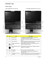
Page 16: ...es Wireless function Indicates the status of wireless LAN communications 5 Bluetooth communication button Enable disables Bluetooth function Indicates the status of Bluetooth communications 6 N A Micr...

Page 17: ...PDIF support Connects to audio line out devices e g speakers headphones 5 Power indicator Indicates the computer s power status 6 Battery indicator Indicates the computer s battery status 7 Bluetooth...

Page 18: ...n the computer is turned off Icon Item Description 1 N A PC Card slot eject button Ejects the PC Card from the slot 2 PC Card slot Accepts one Type II PC Card 3 5 in 1 card reader Accepts Memory Stick...

Page 19: ...ut 2 External display VGA port Connects to an external display device e g external monitor LCD projector 3 Modem RJ 11 port Connects to a phone line 4 Ethernet RJ 45 port Connects to an Ethernet 10 10...

Page 20: ...after prolonged use 5 N A Memory compartment Houses the computer s main memory 6 N A PCI Express Mini Card bay Houses the computer s PCI Express Mini card 7 N A Hard disk bay Houses the computer s har...

Page 21: ...ion Fn F1 Hot key help Displays help on hot keys Fn F2 Acer eSetting Launches the Acer eSettings in Acer Empowering Technology Fn F3 Acer ePower Management Launches the Acer ePower Management in Acer...

Page 22: ...ress the key on the bottom right side of the keyboard or hold Shift and then press the US dollar sign on the number four key Note This function varies according to the language settings Fn F7 Touchpad...

Page 23: ...ps Lock Lights up when Caps Lock is activated Num Lock Lights up when Num Lock is activated Power Lights when the computer is on Battery Lights when the battery is being charged Bluetooth Indicates th...

Page 24: ...Internet programs they can be redefined by users To set the web browser mail and programmable buttons run the Acer Launch Manager Easy launch button Default application Acer Empowering Technology user...

Page 25: ...g on the right scroll bar of windows applications Note Keep your fingers as well as the surface of the touchpad dry and clean The touchpad is sensitive to your finger movements the lighter the touch t...

Page 26: ...t extends battery power via versatile usage profiles Acer ePresentation Management connects to a projector and adjusts dispaly settings conveniently For more information press the key to launch the Em...

Page 27: ...sword is a master password that can decrypt any file on the system The file specific password is assigned when you encrypt each individual file Acer eDataSecurity Management setup wizard will prompt f...

Page 28: ...18 Chapter 1...

Page 29: ...em Optical drive devices includes any kind of CD ROM or DVD ROM drives Floppy disk drives 3 5 inch disks only To activate Acer eLock Management a password must be set at first Once set you may apply l...

Page 30: ...performance of the Acer notebook It provides you with the following options to enhance overall system performance Memory optimization releases unused memory and checks memory usage Disk optimization...

Page 31: ...ata backup Backup to HDD set recovery point Backup to CD or DVD Image or data recovery tools Recovery from a hidden partition factory defaults Recovery from the HDD most recent user defined recovery p...

Page 32: ...ize your Windows operating system so your computer runs faster smoother and better Provides a simple graphical user interface for navigating through the program effortlessly Displays general system st...

Page 33: ...omatically detects the best settings for a new location while offering you the freedom to manually adjust the settings to match your needs simply by right clicking on the icon in the task bar Acer eNe...

Page 34: ...24 Chapter 1...

Page 35: ...f Wireless LAN Bluetooth CardBus Memory Card Audio and Wired LAN DC mode To suit your usage there are four pre defined profiles Entertainment Presentation Word Processing and Maximum Battery Or you ca...

Page 36: ...26 Chapter 1...

Page 37: ...Chapter 1 27 Acer ePresentation Management Acer ePresentation Management lets you select from two of the most common projector resolution XGA and SVGA...

Page 38: ...am The Acer OrbiCam rotates 225 degrees counterclockwise to achieve the desired angle Refer to the illustrations below Note Do not rotate the camera clockwise to prevent it from the damage For your co...

Page 39: ...corner of the capture window then select the desired resolution Note Setting the camera resolution to 640 x 480 or larger does not change the capture window size Options Click Options to display the...

Page 40: ...ppear Device Settings allows you to change the camera brightness contrast hue saturation sharpness etc Advanced Settings allows you to achieve gain control implement image mirror select image enhancem...

Page 41: ...feature You can now broadcast from your location to an IM partner anywhere in the world Enabling the Acer VisageON for 1 3 megapixel camera models only The Acer VisageON technology comes with two feat...

Page 42: ...isageON to display a menu that allows to change the configuration of the camera face tracking and video effects settings Using Video Effects selected models only The Video Settings section allows you...

Page 43: ...vatars you may have to calibrate the face points to achieve better tracking Follow screen instructions in the VisageON to continue Note You may use video effects when using the camera for IM chat vide...

Page 44: ...fined display settings so you can view multiple windows on the same screen To access this function please go to Start All Programs and click on Acer GridVista You may choose any one of the four displa...

Page 45: ...ger Launch Manager allows you to set the four easy launch buttons located above the keyboard You can access the Launch Manager by clicking on Start All Programs Launch Manager to start the application...

Page 46: ...bar highlight Programs and select Norton Antivirus 2 In the Norton Antivirus main window click Scans 3 In the Scans panel click Run Full System Scan 4 When the scan is complete a scan summary appears...

Page 47: ...atio 13 13 12 11 10 L2 cache size MB 2 2 2 2 2 L2 cache speed GHz 2 33 2 16 2 1 83 1 66 Package type pin 478 478 479 478 478 478 Manufacturing technology nm 65 65 65 65 65 Thermal design power 31W 31W...

Page 48: ...Codec Feature Built in Stereo SNR 85 high performance DACs with 95dB SNR A Weighting ADCs with 85dB SNR A Weighting Internal Microphone Two speakers at least 1 5W 30cc for each 2 digital microphone ar...

Page 49: ...launch buttons Internet browser E mail with LED Acer Empowering one user programmable button Item Specification Vendor model name Panasonic Sanyo Sony Battery Type Li Ion Pack capacity 8 cell 2400 mA...

Page 50: ...ype H glare type Typical White Luminance cd m2 200 Typical 200 Typical 200 Typical 200 Typical Contrast Ratio 300 Typical 300 Min 350 Typical 350 Min Response Time Optical Rise Time Fall Time msec 16...

Page 51: ...an 300mVp p Turn on delay time within two seconds at 115 Vac input voltage within two seconds at 115 Vac input voltage Temperature Operating 0 to 40oC Non operating 31 to 60o C Operating 0 to 40oC Non...

Page 52: ...ative humidity gradient 30 per hour max Drive acoustics sound power bels idle 2 4 typical 2 6 max Shock operating Gs max at 0 5 msec 250 Shock nonoperating Gs max at 2 msec 800 Vibration operating 1 0...

Page 53: ...TAPI 6 MMC 3 and SFF8090 Ver5 Revision 1 2 Applicable disc format DVD read DVD 5 9 10 18 DVD ROM DVD Video DVD R 3 95G DVD R 4 7G DVD RW DVD R DVD RW Multi Border DVD R DVD RW Multi Session DVD R DVD...

Page 54: ...5 Applicable disc format DVD read DVD ROM 5 9 10 18 DVD VIDEO DVD AUDIO DVD R DVD R 3 95G DVD R MULTI BORDER DVD RW DVD R DVD R DL DVD R MULTI SESSION DVD RW CD read CD DA CD ROM Mode 1 CD ROM XA Mode...

Page 55: ...I Trax CD and UDF DVD ROM DVD Video DVD Audio DVD R single multi border DVD R single multi session DVD RW DVD RW DVD RAM KODAK Photo CD single and multi session CD Extra CD PLUS Video CD CD text data...

Page 56: ...F2 during POST when Press F2 to enter Setup message is prompted on the left bottom side of the screen There are six prime items in the BIOS Setup Utility They are Information Main Advanced Security B...

Page 57: ...should be shown on this field IDE1 serial number This item will show the serial number of HDD installed on Primary IDE master If no hard disk or other devices are installed on primary IDE master it wi...

Page 58: ...creen is enabled Power on Display Auto During power on process the system will detect if any display device is connected on external video port If any external display device is connected the power on...

Page 59: ...49 Chapter 2 device sequence will be the same as the one defined in the BIOS setup Boot option D2D Recovery It allows the users to enable or disable the disk to disk recovery...

Page 60: ...Password Policy All the passwords will obey the following rules All the passwords can be set or cleared in BIOS Setup Security screen The password entry consists of eight alphanumeric characters At le...

Page 61: ...Password on boot is enabled the system will pop up the password dialog box to ask for the password when the system is powered on or resumes for S4 state If the users fail three times consecutively in...

Page 62: ...e devices to load the operating system It identifies all the bootable devices in the system and attempts to boot them in the order specified Bootable devices include the diskette drive in module bay t...

Page 63: ...the system Exit Discarding Changes The users can exit the Setup not to save changes Load Setup Defaults It allows the users to load default values in CMOS Setup Discard Changes The users can discard...

Page 64: ...preventing electrostatic discharge Small Philips screw driver Flat head screw driver Hexagonal driver Tweezers Note The screws for the different components vary in size During the disassembly process...

Page 65: ...stem are unplugged 3 The battery pack is removed Note There are several types of screws used to secure the main unit The screws vary in length Please refer to the screws table after the flowchart Grou...

Page 66: ...remove the components No Description Part No a SCW HEX NYL I R 40 O 4 40 L5 5 34 00015 081 b SCREW MACH WAFER M2 L4 NI 86 T39V1 002 c SCRW M2 5 6 L CASE U CASE 86 00D28 330 d SCRW M2 L3 86 00D29 620 e...

Page 67: ...NYLOK CR3 86 00E34 738 j SCREW M2 L8 NI NON NYLOK 86 00E35 228 k SCREW M3x4 86 9A524 4R0 86 9A524 4R0 l SCRW M2 4 WAFER NI 86 9A552 4R0 m SCREW NI M2 6L 86 9A552 6R0 n SCRW M2 5 L3 NON NYLOK 86 9A523...

Page 68: ...2 Slide the battery latch hold it then remove the battery Removing the HDD Module 1 Release the three screws fastening the HDD module cover 2 Detach the HDD module cover 3 Release the two screws holdi...

Page 69: ...remove the wireless LAN card 4 Release the two screws securing the RAM cover and remove the RAM cover 5 Press the left and right latches to pop up the memory Removing the Keyboard 1 Open the notebook...

Page 70: ...Chapter 3 60 5 Remove the keyboard and reverse it 6 Carefully pull the keyboard FFC lock then disconnect the keyboard FFC...

Page 71: ...e tape securing the wireless antenna and pull out the wireless antenna 3 Release the two screws securing the LCD hinges on the bottom side 4 Release the two screws fastening the LCD hinges on the rear...

Page 72: ...and disconnect the touch pad FFC 2 Release the connector lock and disconnect the function keyboard FFC 3 Release the three screws securing the upper case 4 Release the 27 screws holding the lower cas...

Page 73: ...Release the FFC lock and disconnect the function keyboard FFC 2 Release the four screws holding the function keyboard bracket 3 Then remove the function keyboard bracket 4 Carefully disconnect the mic...

Page 74: ...1 Carefully release the FFC lock and disconnect the touch pad board FFC 2 There are 13 latches holding the touch pad bracket 3 Unlock those latches with a screw driver as shown then detach the touch...

Page 75: ...odule and remove it 2 Pull the dummy card from the slot and remove it Removing the Main Board 1 Disconnect the fan cable 2 Disconnect the speaker cable and Bluetooth module cable 3 Remove the four scr...

Page 76: ...k 2 Remove the heatsink Removing the Bluetooth Module 1 Detach the bluetooth module from the lower case 2 Carefully disconnect the bluetooth module cable Removing the Speakers 1 Release the four screw...

Page 77: ...efully disconnect the MDC cable 2 Release the two screws securing the MDC board then detach the MDC board 3 Disconnect the MDC board cable Remove the Heatsink Module 1 Release the five screws securing...

Page 78: ...rom the CPU socket LCD Disassembly 1 Remove the eight rubber caps on the LCD bezel and release the eight screws securing the LCD bezel 2 Detach the LCD bezel from the LCD module as shown 3 Release the...

Page 79: ...he four screws securing the LCD panel 6 Detach the LCD panel carefully and reverse it as shown 7 Tear off the tapes holding the LCD panel cable carefully then disconnect the LCD panel 8 Remove the ant...

Page 80: ...Chapter 3 70 9 Release the four screws securing the left LCD bracket then remove the left LCD bracket 10 Repeat the anterior step to remove the right LCD bracket...

Page 81: ...and LCD cable through the latch bar and LCD cover 12 Remove the CCD module cap 13 Remove the CCD module ring 14 Push the CCD module upper case a little bit 15 Then Separate the lower case from the up...

Page 82: ...e 2 Verify the symptoms by attempting to recreate running the diagnostic tests or repeating the same operation 3 Disassemble and assemble the unit without any power sources 4 If any problem occurs you...

Page 83: ...tic diskette and start the diagnostic programs 2 See if CD ROM test is passed when the programs run the CD ROM test 3 Follow the instructions in the message window If errors occur reconnect the connec...

Page 84: ...If the voltage is not correct go to the next step Note An audible noise from the power adaptor does not always indicate a defect 3 If the power on indicator does not light up check the power cord of...

Page 85: ...FPC is connected properly 4 If the main board to switch board FPC is connected correctly then check if the FFC on the touch pad PCB is connected properly 5 If the FFC on the touch pad PCB is connecte...

Page 86: ...he coming pages to indicate the BIOS signals on the screen and the error symptoms classified by functions If the symptom is not included on the list please refer to Undetermined Problems Note Most of...

Page 87: ...m not found Enter Setup and see if fixed disk and drive A are properly identified Diskette drive Hard disk drive Main board Power on indicator turns off and LCD is blank Power source battery pack and...

Page 88: ...ontrol word during warm boot 13h Initialize PCI Bus Mastering devices 14h Initialize keyboard controller 16h 1 2 2 3 BIOS ROM checksum 17h Initialize cache before memory autosize 18h 8254 timer initia...

Page 89: ...2h Test keyboard 54h Set key click if enabled 55h Enable USB devices 58h 2 2 3 1 Test for unexpected interrupts 59h Initialize POST display service 5Ah Display prompt Press F2 to enter SETUP 5Bh Disab...

Page 90: ...floppy controller 8Fh Determine number of ATA drives optional 90h Initialize hard disk controllers 91h Initialize local bus hard disk controllers 92h Jump to UserPatch2 93h Build MPTABLE for multi pro...

Page 91: ...handler C5h PnPnd dual CMOS optional C6h Initialize notebook docking optional C7h Initialize notebook docking late C8h Force check optional C9h Extended checksum optional CAh Redirect Int 15h to enabl...

Page 92: ...y type EDh Initialize Memory size EEh Shadow Boot Block EFh System memory test F0h Initialize interrupt vectors F1h Initialize Run Time Clock F2h Initialize video F3h Initialize System Management Mode...

Page 93: ...d LCD inverter ID LCD inverter LCD cable LCD System board Symptom Error Action in Sequence Indicator incorrectly remains off or on but system runs correctly Reconnect the inverter board Inverter board...

Page 94: ...eyboard Hard disk drive System board The system does not enter hibernation mode and four short beeps every minute Press Fn F4 and see if the computer enters hibernation mode Touchpad Keyboard Hard dis...

Page 95: ...rallel Port in the Onboard Devices Configuration of BIOS Setup Utility is set to Enabled Onboard Devices Configuration Run printer self test Printer driver Printer cable Printer System Board Serial or...

Page 96: ...rge or software errors FRU replacement should be considered only when a recurring problem exists When analyzing an intermittent problems follow the procedures below 1 Run the advanced diagnostic test...

Page 97: ...the failing FRU Do not isolate non defective FRU 1 Power off the computer 2 Visually check the devices If any problems are found replace the FRU 3 Remove or disconnect all of the following devices No...

Page 98: ...RT connector 4 RJ11 RJ45 connector 5 MDC module connector 6 MDC board connector 7 Main battery connector 8 ODD connector 9 Mini PCI slot 10 CPU 11 North bridge 12 DIMM slot 13 South bridge 14 HDD conn...

Page 99: ...89 Chapter 5 17 Line out jack 18 Cardbus controller 19 USB connector 20 LAN controller 21 BIOS ROM 22 RTC battery connector 23 5 in 1 card reader No Description No Description...

Page 100: ...cription 1 Keyboard controller 2 Keyboard connector 3 Lid switch connector 4 System fan connector 5 PCMCIA card reader 6 Function key board connector 7 Touch pad board connector 8 Speaker connector 9...

Page 101: ...reasons a part number is changed it will NOT be noted on the printed service guide For Acer authorized service providers your Acer office may have a different part number code from those given in the...

Page 102: ...92 Chapter 6 Exploded Diagram...

Page 103: ...CK LI 6CELL 2 0MAH SONY BTY PACK LI 6C 2 0AH SONY BT 00604 010 BATTERY PACK LI MN 6CELL 2 0MAH SANYO BTY PACK LI MN 6C 2 0AH SANYO BT 00603 021 BATTERY PACK LI MN 6CELL 2 0MAH PANASONIC BTY PACK LI MN...

Page 104: ...MDC1 5 FOXCONNT60M893 0 3 54 TCBV1 001 N A TV TUNER BOARD TV TUNER MINIPCI M103 HYBRID 54 ADFV1 001 TV TUNER BOARD TV TUNER MINIPCI M104 H W ENCO 54 ADFV1 002 CABLE N A BLUETOOTH CABLE B TCABLEHTMYAL...

Page 105: ...BK 27 T30V1 001 POWER CORD 10A 250V 3PIN CHINA BK CORD 10A 250V 3P CHINA BK 27 01518 701 POWER CORD 10A 250V 3PIN CHINA CORD CHINA 10A 250V 3P 27 01518 591 POWER CORD 10A 250V SOUTH AFRICA BK CORD 10A...

Page 106: ...ER MYALL 42 ACKV1 001 DIMM COVER ASSY DIMM COVER MYALL 42 TCBV1 002 LED BOARD SUPPORT BRACKET U CASE SUP BKT L MYALL 33 TCBV1 001 OPTICAL BRACKET ODDBRKTMYALL 33 TCBV1 002 UPPER CASE W COVER SWITCH CA...

Page 107: ...CK LEFT RIGHT HINGE PACK 17 LEFT RIGHT 6K TCBV1 001 LCD BARCKET LEFT BRKT LCD 17 1 L MYALL 33 TCBV1 005 LCD BRACKET RIGHT BRKT LCD 17 1 R MYALL 33 TCBV1 004 N A CAMERA HOLDER HLDR CAMERA SIDE RIM KIRK...

Page 108: ...T IN TOSHIBA TS L632D W O BEZEL S MULT 8X TST TS L632D W O BZL KU 00801 014 DVD RW DRIVE 8X SUPER MULTI SLOT IN LITEON SSM 8515S W O BEZEL S MULTI LTN SSM 8515S BOLSEN E KU 00804 022 DVD RW DRIVE 8X S...

Page 109: ...AH T2400 1 83GMHZ INTEL IC CPU DC YONAH T2400 1 83G PGA KC 24001 DTP CPU DC YONAH T2300 1 66GMHZ INTEL IC CPU DC YONAH T2300 1 66 PGA KC 23E01 DTP CPU YONAH CEL M 430 1 73GNHZ INTEL IC CPU YONAH CEL M...

Page 110: ...800UE 22HCT0 HDD 80GB WD WD800UE 22HCT0 KH 08008 027 HDD 80G 5400RPM TOSHIBA HDD 80GB TOSHIBA 5400RPM KH 08004 006 HDD 80G 5400RPM HITACHI HDD 80G 2 5 5400RPM HGST KH 08007 013 HDD 100G 4200RPM SEAGAT...

Page 111: ...FON CHINESE KB ACF07 002 AS9400 7100 KEYBOARD DARFON SPANISH AS9400 7100 KEYBOARD DARFON SPANISH KB ACF07 003 AS9400 7100 KEYBOARD DARFON THAI AS9400 7100 KEYBOARD DARFON THAI KB ACF07 004 AS9400 7100...

Page 112: ...00 7100 KEYBOARD DARFON NORWAY KB ACF07 018 AS9400 7100 KEYBOARD DARFON DANISH AS9400 7100 KEYBOARD DARFON DANISH KB ACF07 019 AS9400 7100 KEYBOARD DARFON TURKISH AS9400 7100 KEYBOARD DARFON TURKISH K...

Page 113: ...LARE AS 6M ADFV1 013 CAMERA N A CAMERA CMOS 1 3M LOGITECH 961458 2000 L CAMERA CMOS 1 3M 961458 2000 L 56 ABAV1 001 N A CAMERA CMOS 300K VFA BN2QA350K8SD79 CAMERA CMOS VFA BN2QA350K8SD79 56 ADFV1 001...

Page 114: ...HDL 3 7 A SODIMM512MHYS64 T64020HDL 3 7 A KN 51202 021 SDIMM 512M ELPIDA GU33512AGEPN612C SODIMM 512M GU33512AGEPN612C KN 51209 005 SDIMM 512M HYNIX HYMP564S64BP6 C4 SODIMM 512M HYMP564S64BP6 C4 KN 51...

Page 115: ...CR 3 86 00E25 723 N A SCREW SCREW M2 L3 NON NYLOK CR3 86 00E31 723 N A SCREW SCREW M2 5 L6 NYLOK CR3 86 00E33 736 N A SCREW SCREW M2 5 L8 NYLOK CR3 86 00E34 738 N A SCREW SCREW M2 L8 NI NON NYLOK 86...

Page 116: ......

Reviews: