background image

Remote Control Systems


Remote Control Systems 


PAGE: 1 

200, 400, and 500 Series 

Remotes-0214 

2721 NE 4th Ave Pompano FL 33064 | (954) 367-6116  


Visit WWW.ACIHOIST.COM for the most current information


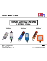
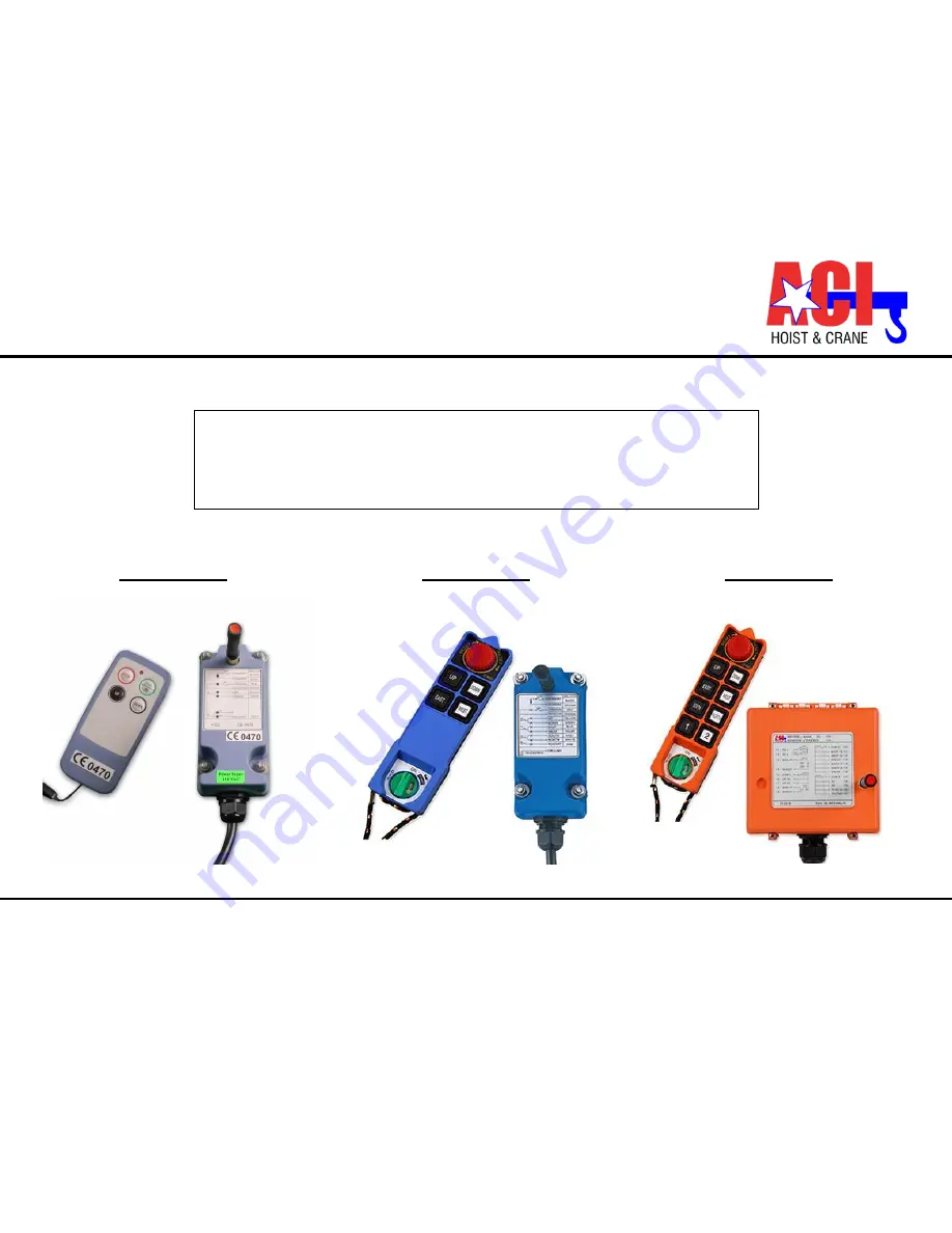
200 Series 


400 Series 

500 Series 


REMOTE CONTROL SYSTEMS 

OPERATION MANUAL 


Summary of Contents for 2002

Page 1: ...ontrol Systems PAGE 1 200 400 and 500 Series Remotes 0214 2721 NE 4th Ave Pompano FL 33064 954 367 6116 Visit WWW ACIHOIST COM for the most current information 200 Series 400 Series 500 Series REMOTE CONTROL SYSTEMS OPERATION MANUAL ...

Page 2: ...3 Inching Operation 11 4 0 FUNCTION SETTINGS DEFINED BY CUSTOMER 12 4 1 Pushbutton Function Setting 12 5 0 CORRESPONDENCE BETWEEN PUSHBUTTON AND RELAY OUTPUT 500 SERIES 16 6 0 ID CODE REMOTE SETTING 500 SERIES 18 7 0 RECEIVER VOLTAGE SELECTION 500 SERIES 20 7 1 Switch the plug to choose voltage 20 8 0 BOARD LAYOUTS 21 8 1 Transmitter PC Board Layout 200 400 Series 21 8 2 Receiver PC Board Layouts ...

Page 3: ...otes 0214 2721 NE 4th Ave Pompano FL 33064 954 367 6116 Visit WWW ACIHOIST COM for the most current information 12 1 3 200 Series Receiver 36 12 1 4 400 Series Receiver 37 12 2 Specifications 38 12 2 1 200 Series 38 12 2 2 400 Series 39 12 2 3 500 Series 40 ...

Page 4: ... abrasive actions improper maintenance or excessive heat Problems resulting from repairs modifications or alterations made by people other than factory or ACI representatives If the product has been abused or damaged due to an accident If repair parts or accessories other than ACI equipment are used on the product they are warranted only to the extent that they are warranted by the manufacturer of...

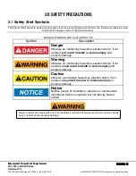
Page 5: ...ates an imminently hazardous situation which if not avoided will result in death or serious injury and property damage Warning Indicates an imminently hazardous situation which if not avoided could result in death or serious injury and property damage Caution Indicates a potentially hazardous situation which if not avoided may result in minor or moderate injury or property damage Notice Notifies p...

Page 6: ...rference 8 Always check transmitter batteries and receiver input power condition before operation 9 The installation and maintenance service is allowed only when the crane and receiver power are off to avoid electrical shock 10 The contents of the manual may be ammended by the manufacturer without notice 11 The specification and function is subject to change without notice by manufacturer 2 2 2 Pr...

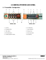
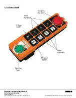
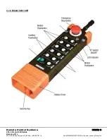
Page 7: ...367 6116 Visit WWW ACIHOIST COM for the most current information 3 0 GENERAL OPERATION 500 SERIES 3 1 Transmitter Configuration 1 Antenna 2 Emergency Stop 3 LED indicator 4 Motor Pushbutton 5 Auxiliary Pushbutton R1 R4 6 F1 Pushbutton 7 Start Pushbutton 8 Battery Cover 9 Rotary Key Switch 10 Security Key ...

Page 8: ...Remote Control Systems PAGE 8 200 400 and 500 Series Remotes 0214 2721 NE 4th Ave Pompano FL 33064 954 367 6116 Visit WWW ACIHOIST COM for the most current information 3 1 1 Model 5008AB ...

Page 9: ...Remote Control Systems PAGE 9 200 400 and 500 Series Remotes 0214 2721 NE 4th Ave Pompano FL 33064 954 367 6116 Visit WWW ACIHOIST COM for the most current information 3 1 2 Model 50011AB ...

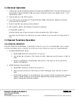
Page 10: ...place 4 remove batteries if not to be used for a long period of time 3 3 Special Functions Operation 3 3 1 Power On Operations Power On means that the Main Relay on the receiver will switch on as soon as the transmitter sends a signal and then the receiver will be on standby for continuous control There are 2 options for Power On Mode 1 Any Pushbutton Power On Mode a Rotate EMS mushroom clockwise ...

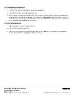
Page 11: ...cceleration pushbutton will accelerate the speed Repeated touch of acceleration pushbutton will increase the speed Note When accelerating the motion pushbutton must be depressed and held in the second speed If motion pushbutton is released there will be no acceleration and speed will return to zero 3 3 3 Inching Operation 1 Start pushbutton is set for inching function 2 Press and hold inching push...

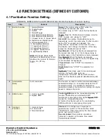
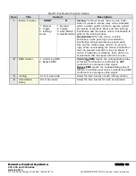
Page 12: ... as OFF Dual Motor 1 When Pushbutton is released from 2nd speed and back to 1st the 1st speed relay is activated again til the Pushbutton is totally released Dual Motor 2 When Pushbutton is released from 2nd speed and back to 1st the 1st speed relay is not activated but bypassed 3 Speed Accel Use START to accelerate to 3 Speed Digital Accel Use START to accelerate to 4 Speed Synthesis Three relays...

Page 13: ...ushbutton will accumulate one speed each time and the relative relay will turn on accord ingly When accelerating the motion Pushbutton must be pressed and held in the 2nd speed If motion Pushbutton is released there will be no acceleration and the speed will return to zero 1 Normal 2 Toggle 3 Inching Accel 1 Normal 2 Toggle 3 Dual Motor 1 4 Dual Motor 2 2 EMS Control 1 Control by EMS 2 Bypass EMS ...

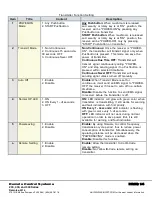
Page 14: ...cted timeframe Continuous Never OFF Transmitter will keep sending signal unless turned off manually 3 Auto Off 1 Enable 2 Disable Enable When Transmit Mode is set for continuous it will send an EMS signal to POWER OFF the receiver if it is set to auto off in a certain timeframe Disable Disable the function to send EMS signal to receiver before the transmitter is off 4 Normal OP LED 1 ON 2 ON Every...

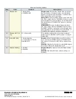
Page 15: ...ontinue operating POWER OFF means the Main Relay and all of the other relays with the NORMAL and Control by EMS functions are going to de energize and it is essential to re commence the procedures of POWER ON again to continue operation 2 Passive Act Tim ing 0 1 4 seconds The duration working time of receiver between passive act is activated and the power or relay is really OFF 3 Auto OFF RX 1 Non...

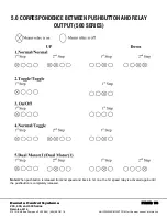
Page 16: ...L 33064 954 367 6116 Visit WWW ACIHOIST COM for the most current information 5 0 CORRESPONDENCE BETWEEN PUSHBUTTON AND RELAY OUTPUT 500 SERIES Note When pushbutton is released from 2nd speed and back to 1st one the 1st speed relay is activated again until the pushbutton is completely released ...

Page 17: ...otes 0214 2721 NE 4th Ave Pompano FL 33064 954 367 6116 Visit WWW ACIHOIST COM for the most current information Note When Up and Down pushbuttons are pressed at the same time the second relay works as Toggle released when they are pressed simultaneously again ...

Page 18: ... or RX when magnetic key is off Note 1 Make sure the power of TX or RX is off when copying 2 The copier can copy both function settings and ID Code but to pair the crystal is still essential to match both TX and RX for communicating with each other ID Code Remote Setting 500 Series ID Code remote setting allows you to pair the new TX or RX if one of them is damaged Using ID Code remote setting wil...

Page 19: ...ote setting fails repeat the instructions above within 4 minutes ID Code remote setting is available for ID Code only It will not change function settings Within the operating distance all same model systems on the same frequency will be paired with the transmitter s ID Code A jumper added inside the receiver is necessary to enable the ID Code remote setting function Model 5008 Model 50011 Jumper ...

Page 20: ...ype Three 3 different AC transformers 48 110 220V 48 220 380V 3 110 220 380V Disconnect the AX s power select the proper voltage and plug in the connector 7 1 Switch the plug to choose voltage Transmitter Battery Information Two 2 AA size alkaline batteries are required for the transmitter The LED will flash green when the battery power is sufficient The LED will flash red when the battery power i...

Page 21: ...h Ave Pompano FL 33064 954 367 6116 Visit WWW ACIHOIST COM for the most current information 8 0 BOARD LAYOUTS 8 1 Transmitter PC Board Layout 200 400 Series Please do not install a VHF crystal into a UHF PC board or vice versa VHF 310 0325 331 1650 MHz UHF 425 5925 446 7250 MHz ...

Page 22: ...motes 0214 2721 NE 4th Ave Pompano FL 33064 954 367 6116 Visit WWW ACIHOIST COM for the most current information 8 2 Receiver PC Board Layouts 200 400 Series Remark The Polarity direction of DC Input is not required when plugging in the power line connector ...

Page 23: ...and 500 Series Remotes 0214 2721 NE 4th Ave Pompano FL 33064 954 367 6116 Visit WWW ACIHOIST COM for the most current information The GND ground of the receiver must be connected with metal part of the equipment or electrical shock may occur ...

Page 24: ...Remote Control Systems PAGE 24 200 400 and 500 Series Remotes 0214 2721 NE 4th Ave Pompano FL 33064 954 367 6116 Visit WWW ACIHOIST COM for the most current information ...

Page 25: ...es Up Down R0 400 Series 3 independent COM lines Up Down East West R0 400 Series 4 independent COM lines Up Down East West North South R0 Please refer to the above figures of receiver relay boards and if an independent COM line is required then cut the wire labeled with a white X The longer part of the wire will become the new COM line Then you may connect this new COM line with an existing spare ...

Page 26: ...both the Transmitter and Receiver Please refer to the procedure below in regard to replacing the crystal 9 1 Procedures 1 Pry up the crystal with a flat screwdriver 2 Remove the crystal from the system 3 Use needle nose pliers to straighten both pins of the new crystal Note Toreplace a new crystal please note there are two kinds of frequencies available UHF and VHF The current frequency band is ma...

Page 27: ... 367 6116 Visit WWW ACIHOIST COM for the most current information 4 Insert the new crystal vertically into the PC board 5 Press the new crystal down into the socket Attention The Transmitter frequency will be different from Receiver frequency For Frequency for TX is 311 MHz Frequency for RX is 321 7 MHz ...

Page 28: ...050 36 319 3950 64 326 8850 9 312 1725 37 319 6625 65 327 1525 10 312 4400 38 319 9300 66 327 4200 11 312 7075 39 320 1975 67 327 6875 12 312 9750 40 320 4650 68 327 9550 13 313 2425 41 320 7325 69 328 2225 14 313 5100 42 321 0000 70 328 4900 15 313 7775 43 321 2675 71 328 7575 16 314 0450 44 321 5350 72 329 0250 17 314 3125 45 321 8025 73 329 2925 18 314 5800 46 322 0700 74 329 5600 19 314 8475 4...

Page 29: ...0 164 442 4450 109 427 7325 137 435 2250 165 442 7125 110 428 0000 138 435 4900 166 442 9800 111 428 2675 139 435 7575 167 443 2475 112 428 5350 140 436 0250 168 443 5150 113 428 8025 141 436 2925 169 443 7825 114 429 0700 142 436 5600 170 444 0500 115 429 3375 143 436 8275 171 444 3175 116 429 6050 144 437 0950 172 444 5850 117 429 8725 145 437 3625 173 444 8525 118 430 1400 146 437 6300 174 445 ...

Page 30: ...T COM for the most current information 9 4 Changing RO START N O normally open INTO N C normally closed The Ro START key of the new 200 400 series provides NO and NC contact The NO is the default setting If a NC output is necessary please remove the 8 wire RO Start color pink from the connector and insert it into 10 Pin Procedures ...

Page 31: ...the manufacturer 3 TXLED flashes red every 2 seconds when any motion pushbutton is pressed The transmitter batteries are at low power Replace the 2 AA size Alkaline batteries at once 4 RXError LED flashes red slowly every 0 5 sec The memory of the RX is defective Send back to the manufacturer 5 The operating dis tance is shorter or an intermittent operation is happening It was interferred by other...

Page 32: ... N O 2 The fuse for the power AC48 110 220 380V is 0 25A The fuse for the power DC 12 24V is 1 5A 3 The fuse for the AC type at the COM main is 10A The fuse for the DC type at the COM main is 20A 4 The com lines have been arranged prior to shipment if an independent com line is required please refer to section 8 3 Note The polarity direction for the power of DC12 24V is not required when plugging ...

Page 33: ...64 954 367 6116 Visit WWW ACIHOIST COM for the most current information Wiring Diagram 500 Series Model 5008 Default wiring diagram shown Custom programming might alter relay outputs Wiring Diagram 500 Series Model 50011 Note Default wiring diagram shown Custom programming might alter relay outputs ...

Page 34: ...s PAGE 34 200 400 and 500 Series Remotes 0214 2721 NE 4th Ave Pompano FL 33064 954 367 6116 Visit WWW ACIHOIST COM for the most current information 12 0 DIMENSIONS SPECIFICATIONS 12 1 Dimensions 12 1 1 500 Series Model 5008 ...

Page 35: ...Remote Control Systems PAGE 35 200 400 and 500 Series Remotes 0214 2721 NE 4th Ave Pompano FL 33064 954 367 6116 Visit WWW ACIHOIST COM for the most current information 12 1 2 500 Series Model 50011 ...

Page 36: ...ote Control Systems PAGE 36 200 400 and 500 Series Remotes 0214 2721 NE 4th Ave Pompano FL 33064 954 367 6116 Visit WWW ACIHOIST COM for the most current information 12 1 3 200 Series Receiver Transmitter ...

Page 37: ...ote Control Systems PAGE 37 200 400 and 500 Series Remotes 0214 2721 NE 4th Ave Pompano FL 33064 954 367 6116 Visit WWW ACIHOIST COM for the most current information 12 1 4 400 Series Receiver Transmitter ...

Page 38: ...buttons Start Stop Up Down East West 2006 6 single step pushbuttons Start Stop Up Down North South East West General Specifications Frequency Control Crystal Low Power Indicator Pushbutton Jammed Detector Operation Range Up to 328 feet 100 meters Operating Temperature 49 F 176 F 45 C 80 C Power Consumption about 1OmW Structure Nylon and Glass Fiber Shock Resistant Function Programmable Transmitter...

Page 39: ...e step pushbuttons Up Down North South East West General Specifications Frequency Control Crystal Low Power Indicator Pushbutton Jammed Detector Operation Range Up to 328 feet 100 meters Operating Temperature 49 F 176 F 45 C 80 C Power Consumption about 1OmW Structure Nylon and Glass Fiber Shock Resistant Function Programmable Transmitter Specifications L X W x H 6 42 X 1 93 X 1 77 163 X 49 X 45 m...

Page 40: ...e fuse kit and instruction manual This radio has programmable operation 5008 8 double step pushbuttons Start EMS Transmitter Specifications 5008 L X W X H 6 42 X 1 93 X 1 77 163 X 49 X 45 mm Weight 0 61 lbs 0 3 kg with batteries Two 2 AA size batteries 50011 L X W X H 10 79 X 3 03 X 1 65 274 X 77 X 42 mm Weight 1 19 lbs 0 5 kg with batteries Four 4 AA size batteries General Specifications Frequenc...

Reviews: