maestro
clocked modulation controller
firmware version 1.0
65mA +12 / 18mA -12
20 HP / 25mm Deep
Reverse Power Protection
Made in USA
We guarantee our products to be free from manufacturing defects (materials or workmanship) for one year from the date of the
original retail purchase (receipt or invoice required). For more information please visit www.acidraintechnology.com.
About Maestro
Maestro is a 6 channel clocked modulation controller
inspired by the automation lanes found in digital audio
workstation software, brought into eurorack and made
playable and performable. Maestro will push and pull
the parameters of your other modules with rapid or
slowly evolving voltages, always in perfect sync with
eachother and the rest of your system.
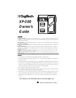
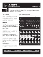
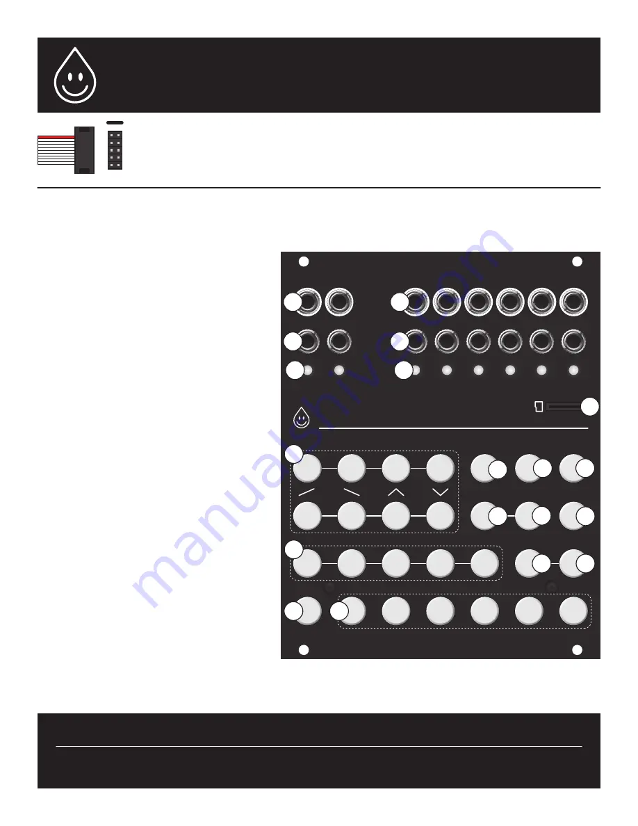
Hardware
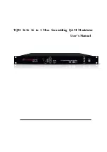
Maestro is comprised of 6 identical channels, each with
an output (4), gate or trigger input (5), output state LED
(6) and channel button (19). Maestro’s tempo is
displayed in 4 pulses per quarter note on the clock LED
(3) and the module can be externally clocked and reset
on inputs (2). Maestro’s clock and reset signals are
present on outputs (1).
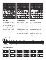
Each channel is assigned a clock division or
multiplication from the timing buttons (15) that can be
modified by the triplet (16) or slow (17) buttons. See
diagram of timings on next page.
Each channel is assigned a waveform from the
waveform buttons (8) that can be modified by the
smooth (12) and bipolar (13) buttons. Bipolar changes a
channel’s output between 0 to +5V and -5V to +5V. See
diagrams of waveforms on next page.
Mute (18) will mute or unmute selected channels.
Chain (14) enters the chain menu where multiple
waveforms can be sequenced in a row. See description
on next page.
Clock (11) enters the clock settings menu. See
description on next page.
Save (9) and load (10) enter the save and load menus
where channel settings can be saved and recalled from
the micro SD card (7). See description on next page.
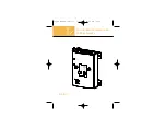
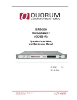
-12 red
Maestro requires a +12V / -12v power supply with a 2x5 pin ribbon cable (included). The red line of the ribbon
cable must be aligned with the -12V marking next to the module’s power header and on your case’s power
distribution board. Maestro draws 65mA from the +12 rail and 18mA from the -12 rail. Please ensure you have
enough power available before installing.
maestro
re
s
et
I
II
III
IV
V
VI
clock
mute
1
/2
I
II
III
IV
V
triplet
s
l
ow
smooth
bipolar
VI
chain
clock
1/4
1
/8
1/16
high
low
squ
are
random
1
/32
save
load
Quick Reference Guide
full manual available on acidraintechnology.com
7
4
5
6
1
2
3
18
9
10
11
12
13
14
16
17
15
8
19