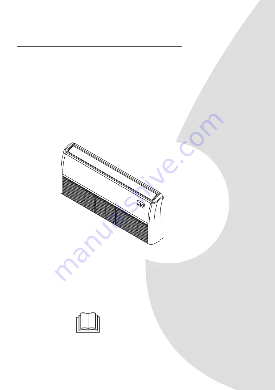
background image

Owner’s Manual & 
Installation Manual

ACIQ-18FM-HH-MB, ACIQ-24FM-HH-MB

ACiQ Floor or Ceiling Mounted Air Handler

IMPORTANT NOTE:

Read this manual


carefully before installing or 

operating your new


air conditioning unit. Make 

sure to save this


manual for future reference.

Summary of Contents for ACIQ-18FM-HH-MB

Page 1: ...ual ACIQ 18FM HH MB ACIQ 24FM HH MB ACiQ Floor or Ceiling Mounted Air Handler IMPORTANT NOTE Read this manual carefully before installing or operating your new air conditioning unit Make sure to save this manual for future reference ...

Page 2: ...cifications and Features 07 Owner s Manual Table of Contents Safety Precautions 04 Care and Maintenance 17 Troubleshooting 19 Indoor unit display 07 Operating Temperature 15 Other features 16 Remote Control 09 ...

Page 3: ...ect installation location 2 Install drain joint 3 Anchor outdoor unit Refrigerant Piping Connection A Note on Pipe Length B Connection Instructions Refrigerant Piping 1 Cut pipe 2 Remove burrs 3 Flare pipe ends 4 Connect pipes Wiring 1 Outdoor Uint Wiring 2 Indoor Uint Wiring Air Evacuation 1 Evacuation Instructions 2 Note on Adding Refrigerant Test Run 22 23 24 25 25 27 29 29 30 30 31 31 33 33 34...

Page 4: ...ng smell immediately turn off the unit and disconnect the power Call your dealer for instructions to avoid electric shock fire or injury Do not insert fingers rods or other objects into the air inlet or outlet This may cause injury since the fan may be rotating at high speeds Do not use flammable sprays such as hair spray lacquer or paint near the unit This may cause fire or combustion Do not oper...

Page 5: ...ension cord to power the unit Do not share the electrical outlet with other appliances Improper or insufficient power supply can cause fire or electrical shock If connecting power to fixed wiring an all pole disconnection device which has at least 3mm clearances in all poles and have a leakage current that may exceed 10mA the residual current device RCD having a rated residual operating current no...

Page 6: ...l the appliance to its support please read the information for details in indoor unit installation and outdoor unit installation sections For units that have an auxiliary electric heater do not install the unit within 1 meter 3 feet of any combustible materials Do not install the unit in a location that may be exposed to combustible gas leaks If combustible gas accumulates around the unit it may c...

Page 7: ...ALARM OPERATION DEF FAN Infrared receiver MANUAL TIMER ALARM OPERATION DEF FAN Illustrations in this manual are for explanatory purposes The actual shape of your indoor unit may be slightly different The actual shape shall prevail NOTE Different models have different display panel Not all the indicators describing below are available for the air conditioner you purchased Please check the indoor di...

Page 8: ...UTO FORCED COOL OFF FORCED COOL mode In FORCED COOL mode the Operation light flashes The system will then turn to AUTO after it has cooled with a high wind speed for 30 minutes The remote control will be disabled during this operation OFF mode The unit turns off OPERATION OPERATION Operation indicator Timer indicator TIMER TIMER PRE DEF indicator pre heating defrost Alarm indicator Func button ALA...

Page 9: ... is O 86 F TEMP Decreases temperature in O 1 F 1 C increments Min temperature is O 62 F TIMER ON Sets timer to turn unit on TIMER OFF Sets timer to turn unit off SWING DIRECT Starts and stops up down airflow louver movement LED FOLLOW ME Temperature sensing and room temperature display button SELF CLEAN Starts and stops self clean feature ON OF F T E MP FP TIMER ON TIMER OFF MODE FAN SLC SLEEP TUR...

Page 10: ...display ECO display Displays when SLEEP function is activated FOLLOW ME display Indicates that the FOLLOW ME function is on FAN SPEED display Displays selected FAN SPEED HIGH MED or LOW This display is blank when set to AUTO speed or DRY mode Temperature Timer display Displays the set temperature by default or timer setting when using TIMER ON OFF functions o Temperature range 62 86 F Timer settin...

Page 11: ...ansmitting a command from the remote control to the unit be sure to point the control toward the right side of the unit The unit confirms receipt of a command by sounding an audible beep 1 Turn the unit on by pushing the ON OFF button 2 If there is a preference for C rather than F default press and hold the increase and decrease temperature set point buttons together for approximately 3 seconds 3 ...

Page 12: ...essing the FAN button NOTE When the unit is on the fan runs continuously in cooling or heating When in heating there might be situations where the fan will slow down or shut off to prevent cold blow Selecting the up down airflow Louver Position To optimize comfort the up down aiflow louver operates in a preset range as shown in the following figure COOLING HEATING Fig 10 Louver Position The up dow...

Page 13: ...e UNIT OFF a Set the TIMER off as described in the UNIT ON section The TIMER display on the unit illuminates and the unit remains off b Adjust the TIMER ON settings to 0 0 to cancel this option Timer ON and Timer OFF Use both functions to program the unit to turn on and shut off at specified times UNIT OFF a Set TIMER ON as previously described b Set TIMER OFF as previously described The unit star...

Page 14: ...ion the compressor operates at a low frequency and the indoor unit produces a faint breeze which reduces the noise to the lowest level Due to the low frequency operation of the compressor it may result in insufficient cooling and heating capacity LED Light Press LED to turn the display light on and off Resetting the Remote Control If the batteries in the remote control are removed the current sett...

Page 15: ...perature 17 C 32 C 62 F 90 F 0 C 30 C 32 F 86 F 10 C 32 C 50 F 90 F Outdoor Temperature 18 C 43 C 64 F 109 F 7 C 24 C 19 F 75 F 11 C 43 C 52 F 109 F 7 C 43 C 19 F 109 F For models with low temp cooling systems 18 C 43 C 64 F 109 F 18 C 52 C 64 F 126 F For special tropical models 18 C 52 C 64 F 126 F For special tropical models COOL mode HEAT mode DRY mode COOL mode HEAT mode DRY mode Room Temperat...

Page 16: ...ree minute protection feature some models A protection feature prevents the air conditioner from being activated for approximately 3 minutes when it restarts immediately after operation Louver Angle Memory Function some models Some models are designed with a louver angle memory function When the unit restarts after a power failure the angle of the horizontal louvers will automatically return to th...

Page 17: ...o clean the filter once every two weeks WARNING DO NOT REMOVE OR CLEAN THE FILTER BY YOURSELF Removing and cleaning the filter can be dangerous Removal and maintenance must be performed by a certified technician 1 Open the air intake with a screwdriver or similar tool Detach the grille from the main unit by holding the grille at a 45 angle lifting it up slightly and then pulling the grille forward...

Page 18: ...eaks Replace batteries Make sure nothing is blocking all air inlets and outlets CAUTION Before changing the filter or cleaning turn off the unit and disconnect its power supply When removing filter do not touch metal parts in the unit The sharp metal edges can cut you Do not use water to clean the inside of the indoor unit This can destroy insulation and cause electrical shock Do not expose filter...

Page 19: ...d contraction of the unit s plastic parts Both the indoor unit and outdoor unit make noises Low hissing sound during operation This is normal and is caused by refrigerant gas flowing through both indoor and outdoor units Low hissing sound when the system starts has just stopped running or is defrosting This noise is normal and is caused by the refrigerant gas stopping or changing direction Squeaki...

Page 20: ... detailed description of the unit malfunction as well as your model number Troubleshooting When troubles occur please check the following points before contacting a repair company Problem Possible Causes Solution Poor Cooling Performance Temperature setting may be higher than ambient room temperature Lower the temperature setting The heat exchanger on the indoor or outdoor unit is dirty Clean the ...

Page 21: ...emely low Use auxiliary heating device Cold air is entering through doors and windows Make sure that all doors and windows are closed during use Low refrigerant due to leak or long term use Check for leaks re seal if necessary and top off refrigerant Indicator lamps continue flashing The unit may stop operation or continue to run safely If the indicator lamps continue to flash or error codes appea...

Page 22: ...19 3 4in Φ22 7 8in 2 4 1 Name of Accessories Q ty pc Shape 1 2 depending on models 1 1 1 1 1 1 Name of Accessories Q ty pc Shape 1 2 1 2 Battery some models Soundproof insulation sheath some models Outlet pipe sheath some models Outlet pipe clasp some models Drain joint some models Seal ring some models Magnetic ring wrap the electric wires S1 S2 P Q E around the magnetic ring twice some models Ma...

Page 23: ...Install the drainpipe L L1 N L2 1 2 3 4 5 MC MC 6 7 Install the indoor unit Evacuate the refrigeration system Connect the wires Connect the refrigerant pipes Perform a test run Page 23 Installation Summary Installation Summary ...

Page 24: ... prevail NOTE The installation must be performed in accordance with the requirement of local and national standards The installation may be slightly different in different areas Unit Parts Display panel Drain pipe Installation part Connecting pipe Air inlet Air outlet Remote controller Air flow louver at air outlet Air inlet with air filter in it 1 2 4 3 6 7 8 8 9 5 1 2 3 4 5 6 7 8 9 ...

Page 25: ...d wiring have been completed Enough room exists for installation and maintenance Enough room exists for the connecting the pipe and drainpipe The ceiling is horizontal and its structure can sustain the weight of the indoor unit The air inlet and outlet are not blocked The airflow can fill the entire room There is no direct radiation from heaters DO NOT install unit in the following locations Areas...

Page 26: ...door parts installation size MODEL Btu h Length of A mm inch Length of B mm inch 18K 24K 1068 42 675 26 6 30K 48K 1285 50 6 675 26 6 36K 48K 1650 65 675 26 6 48K 60K 1650 65 675 26 6 Length of C mm inch Length of D mm inch Length of E mm inch 235 9 3 983 38 7 220 8 7 235 9 3 1200 47 2 220 8 7 235 9 3 1565 61 6 220 8 7 235 9 3 1565 61 6 220 8 7 ...

Page 27: ...hoosing where to start determine the direction of the pipes to be drawn out Especially in cases where there is a ceiling involved align the refrigerant pipes drain pipes and indoor and outdoor lines with their connection points before mounting the unit 2 The installation of hanging screw bolts 3 After the selection of the installation location position the refrigerant pipes drain pipes and indoor ...

Page 28: ...iquid side The conduit installation plate Cord conduit Side board The conduit installation plate screws not supply screws not supply The conduit installation plate Chassis Hanging arm Hanging screw bolt Wall Mounted Installation How to install the conduit installation plate if supplied 1 Fix the sheath connector not supply on the wire hole of the conduit installation plate 2 Fix the the conduit in...

Page 29: ...Insulate all piping to prevent condensation which could lead to water damage If the drainpipe is bent or installed incorrectly water may leak and cause a water level switch malfunction In HEAT mode the outdoor unit will discharge water Ensure that the drain hose is placed in an appropriate area to avoid water damage and slippage DO NOT pull the drainpipe forcefully This could disconnect it NOTE ON...

Page 30: ... air outlet fan is at a 90 angle to the direction of the wind If needed build a barrier in front of the unit to protect it from extremely heavy winds See Figures below Strong wind Strong wind Strong wind If the unit is frequently exposed to heavy rain or snow Build a shelter above the unit to protect it from the rain or snow Be careful not to obstruct air flow around the unit If the unit is freque...

Page 31: ...see Fig B do the following 1 Insert the drain joint into the hole in the base pan of the unit The drain joint will click in place 2 Connect a drain hose extension not included to the drain joint to redirect water from the unit during heating mode Seal Drain joint A B Base pan hole of outdoor unit Seal IN COLD CLIMATES In cold climates make sure that the drain hose is as vertical as possible to ens...

Page 32: ...810x420 37 24x31 9x16 53 673 26 5 403 15 87 946x810x410 37 24x31 9x16 14 673 26 5 403 15 87 952x1333x410 37 5x52 5x16 14 634 24 96 404 15 9 952x1333x415 37 5x52 5x16 34 634 24 96 404 15 9 845x702x363 33 27x27 6x14 3 540 21 26 350 13 8 938x1369x392 36 93x53 9x15 43 634 24 96 404 15 9 900x1170x350 35 4x46x13 8 590 23 2 378 14 88 800x554x333 31 5x21 8x13 1 514 20 24 340 13 39 890x673x342 35x26 5x13 4...

Page 33: ...g Maximum drop height North America Australia and the eu frequency conversion Split Type 15K 25 82 10 32 8 15K 24K 30 98 4 20 65 6 24K 36K 50 164 25 82 36K 60K 65 213 30 98 4 Other Split Type 12K 15 49 8 26 18K 24K 25 82 15 49 30K 36K 30 98 4 20 65 6 42K 60K 50 164 30 98 4 Refrigerant Piping Connection Oil traps CAUTION If oil flows back into the outdoor unit s compressor this might cause liquid c...

Page 34: ... pipe The end of the pipe must extend beyond the flare form Flare form Pipe Step 2 Remove burrs Burrs can affect the air tight seal of refrigerant piping connection They must be completely removed 1 Hold the pipe at a downward angle to prevent burrs from falling into the pipe 2 Using a reamer or deburring tool remove all burrs from the cut section of the pipe Pipe Reamer Point down 6 Place flaring...

Page 35: ... cable signal cable and the piping together with binding tape NOTE DO NOT intertwine signal cable with other wires While bundling these items together do not intertwine or cross the signal cable with any other wiring 7 Thread this pipeline through the wall and connect it to the outdoor unit 8 Insulate all the piping including the valves of the outdoor unit 9 Open the stop valves of the outdoor uni...

Page 36: ...e same power circuit 16 Connect the outdoor wires before connecting the indoor wires 7 Only connect the unit to an individual branch circuit outlet Do not connect another appliance to that outlet 8 Make sure to properly ground the air conditioner 9 Every wire must be firmly connected Loose wiring can cause the terminal to overheat resulting in product malfunction and possible fire Do not let wires...

Page 37: ...purchased seperately purchased seperately Indoor unit power wires Indoor Outdoor connective wires Outdoor unit power wires Indoor unit Outdoor unit Air switch purchased seperately purchased seperately Indoor unit power wires Indoor Outdoor connective wires B C Indoor unit Outdoor unit Air switch Air switch purchased seperately Only for the North American purchased seperately purchased seperately O...

Page 38: ...ls with the labels on the terminal block Firmly screw the u lug of each wire to its corresponding terminal Refer to the Serial Number and Wiring Diagram located on the cover of the electric control box 3 Connect the u lugs to the terminals Match the wire colors labels with the labels on the terminal block Firmly screw the u lug of each wire to its corresponding terminal 4 Clamp down the cable with...

Page 39: ... 32 25 50 40 70 55 70 60 MODEL Btu h 36K 37K 60K 36K 37K 60K POWER PHASE 3 Phase 3 Phase 3 Phase 3 Phase 380 420V 380 420V 208 240V 208 240V CIRCUIT BREAKER FUSE A 25 20 32 25 32 25 45 35 MODEL Btu h 18K 19K 24K 25K 36K 37K 48K 49K 60K POWER PHASE 1 Phase 1 Phase 1 Phase 1 Phase 1 Phase 208 240V 208 240V 208 240V 208 240V 208 240V CIRCUIT BREAKER FUSE A 25 20 32 25 50 40 70 55 70 60 MODEL Btu h 36...

Page 40: ...5 10 15 10 15 10 15 10 15 10 POWER outdoor PHASE 1 Phase 1 Phase 1 Phase 1 Phase 1 Phase 208 240V 208 240V 208 240V 208 240V 208 240V CIRCUIT BREAKER FUSE A 25 20 25 20 40 30 50 40 50 40 MODEL Btu h 36K 37K 60K 36K 37K 60K POWER indoor PHASE 1 Phase 1 Phase 1 Phase 1 Phase 208 240V 208 240V 208 240V 208 240V CIRCUIT BREAKER FUSE A 15 10 15 10 15 10 15 10 POWER outdoor PHASE 3 Phase 3 Phase 3 Phase...

Page 41: ...acuum for at least 15 minutes or until the Compound Meter reads 76cmHG 105 Pa 2 3 4 5 6 Close the Low Pressure side of the manifold gauge and turn off the vacuum pump 7 Wait for 5 minutes then check that there has been no change in system pressure 8 If there is a change in system pressure refer to Gas Leak Check section for information on how to check for leaks If there is no change in system pres...

Page 42: ...ipe length x 40g 0 42oZ m ft φ6 35 1 4 φ9 52 3 8 φ12 7 1 2 R22 orifice tube in the indoor unit Total pipe length standard pipe length x 30g 0 32oZ m ft Total pipe length standard pipe length x 65g 0 69oZ m ft Total pipe length standard pipe length x 115g 1 23oZ m ft R22 orifice tube in the outdoor unit Total pipe length standard pipe length x15g 0 16oZ m ft Total pipe length standard pipe length x...

Page 43: ...ered correctly d Ensure the indicators on the remote control and the display panel on the indoor unit work properly e Ensure the manual buttons on the indoor unit works properly f Check to see that the drainage system is unimpeded and draining smoothly g Ensure there is no vibration or abnormal noise during operation 5 For the Outdoor Unit a Check to see if the refrigeration system is leaking b Ma...

Page 44: ... and specifications are subject to change without prior notice for product improvement Consult with the sales agency or manufacturer for details Any updates to the manual will be uploaded to the service website please check for the latest version ...

Reviews: