Electrocorder EC-7VAR-RS
Dual Current Range - User Instructions
WARNING!
THIS PRODUCT MUST ONLY BE USED BY SUITABLY
QUALIFIED PERSONNEL; DO NOT ATTEMPT TO USE THIS
PRODUCT UNLESS YOU ARE QUALIFIED TO DO SO.
HIGH VOLTAGES THAT CAUSE BURNS AND LETHAL SHOCKS
ARE
PRESENT
DURING
VOLTAGE
MONITORING
AND
RECORDING!
Voltage inputs are not isolated from each other, as
one input is energised, other will become live!
General Description
Thank you for purchasing the Electrocorder EC-7VAR-RS, we hope you enjoy using this
product, this package consists of seven main components:
1. Electrocorder logger (1)
The logging unit is housed in a strong ABS case.
2. Carry Case (1)
The ABS case of the logging unit is in turn contained within a soft carry case.
3. Voltage Input Leads (4)
Four voltage input leads are provided to allow easy connection to the voltage system.
4. Current Sensors (3)
Three current sensors are provided.
5. USB Lead (1)
A USB lead is provided to allow connection between the logger and any modern PC.
6. Software (download free from www.electrocorder.com)
Electrosoft software is provided free.
7. User Instructions (1)
These User Instructions are provided to give guidance, to qualified personnel.
PC Hardware requirements
To run Electrosoft you must have certain hardware and software installed on your
computer. The system requirements include:-
An IBM
®
- compatible Personal Computer with a minimum of an 80486 processor.
A hard disk, with at least 5MB spare capacity.
One CD/DVD drive.
An SVGA 1024 x 768 or higher resolution display.
At least 16MB of random access memory (RAM).
A mouse.
Microsoft
®
Windows 9X, NT4.0, 2000, XP, Vista, Windows 7, 8, 10
Installing Electrosoft
When you run the Setup program, it will automatically set a path on your hard disk and
install Electrosoft there.
In Windows 9X, NT4.0, 2000, XP, Vista, Windows 7, 8, 10 the Setup program will create
an option in your Programs menu, which is in the Start menu.
Step 1:
To install Electrosoft; run Setup.
For Windows 9X, NT4.0, 2000, XP, Vista, Windows 7.
Step 2:
From the Taskbar menu click Start and choose Run. The Run dialogue box
appears.
Step 3:
Type a:\Setup. Click OK. Follow the instructions on the screen to install
Electrosoft - you will be alerted when the installation is complete.
Getting started
In order to set-up an Electrocorder, you must first run Electrosoft on your PC. Then connect
an Electrocorder to the PC serial port using the correct (supplied) serial lead. In Electrosoft,
use the ‘Setup’ dialog box window and input the details of the location to be monitored. The
Electrocorder does NOT need to be connected in to the mains voltage to perform this task.
The recording mode is set by default to commence recording when the Electrocorder
“Start”
button is pressed, and to stop recording when the memory is full. This logger can be used to
record voltage and current separately. When recording voltage, the logger will take power
from the voltage supply, however when logging only current, battery life will be reduced,
where possible use a voltage input.
Select the recording method - two options are available:
1. Record to EN50160 standard - the Electrocorder will take 16 samples per channel per
cycle for 10 minutes. It then averages the samples taken over that 10 minute period and
stores the TRMS values as well as single Max and Min values for each channel. In this
mode the unit will record for approximately 50 days until the memory is full.
2. Take a sample over a discrete period - the Electrocorder can be set to take an average
over a selected period, 2 (two) sec to 60 (sixty) minutes and also record the max and min
during each period. For example,
a unit set to record every 2 (two) seconds will record
for approximately 4 hours
. A unit set to record every 12 seconds will record for
approximately 1 day.
A unit set to record every 60 (sixty) minutes will record for
approximately 300 days.
When the required information has been input, download to the connected Electrocorder by
clicking the ‘Write Setup’ icon. The Electrocorder is now ready to monitor voltage.
DUAL RANGE
The range can only be changed when the logger has started logging. The presently
selected range will automatically be displayed if power supply is connected to the
voltage inputs. If no power is connected pres
sing the “?” button will display the
range, either 5A to 400A or 30A to 3k
A. To change the range, press and hold the “?”
button and press the adjacent up/down arrow, this will toggle the range. Please note
that the range should be set once at the beginning of recording and not changed, the
logger does not record which range it was in so you should make note of the range
used.
When the Electrocorder is recording a flashing green light will flash and when it has
completed recording, a red light will appear on the unit. If both red and green LEDs are
illuminated when connected to voltage, this signifies a ‘reset’, the battery may have been
dislodged, check the battery, then again set-up the logger to record.
When the Electrocorder is recording with voltage connected a flashing green light will show,
NOTE the green LED will not flash when there is no voltage connected! When it has
completed recording, a steady red light will appear on the unit. The database contained
within Electrosoft will also advise that the unit has completed recording and is ready to be
collected. To download the recorded data connect the Electrocorder to the PC serial port
and click the ‘Read Setup’ icon. The recorded data is displayed for analysis.
This document is produced in conjunction with the Help file contained in Electrosoft, which
contains a detailed explanation of all features and contains information, which should be
studied prior to using this product.
When installed, make a note of the serial or COM port number the converter has been
assigned to and when you run Electrosoft, select the appropriate serial port or COM port
number.
SAFETY TIPS
Voltage inputs are labelled ‘L1’, ‘L2’, ‘L3’ and Neutral is labelled ‘N’. For correct operation
this recorder must have a proper
Neutral (N) connection. Current inputs are labelled ‘A1’,
‘A2’ & ‘A3’. Use correct and approved safety clothing including goggles and gloves!
Prior to connection of the logger to any voltage system:-
1) Electrically isolate the conductors to which you wish to connect.
2) Remove (unplug) all voltage leads from the logger.
3) Current input sensors must only be used around insulated conductors, the arrows on the
Rogowski Coils should point in the direction of the load.
4) Using insulating gloves, connect the each current sensor in turn around each current
carrying conductor.
5) Using insulating gloves, connect the each voltage lead in turn to the electrical bus-bar
with the crocodile clip.
6) When all voltage leads are connected to the voltage bus-bars, then beginning with the
Neutral (N) input, connect in turn each lead to the logger (with the 4mm shrouded plugs).
7) As you connect L1, L2 and L3 there will be a visual light indication should voltage be
present on the input.
8) Voltage leads are double layer. The inner layer is white, should the lead become scuffed
and/or damaged, the white inner layer should become visible, as opposed to the normal red
or black outer layer. When this occurs, you must replace the voltage lead with a new,
undamaged one.
Features & Benefits of the EC-7VAR Logger System
Feature
Benefit
Unit is small and lightweight.
Quick and easy to install
Easy to use Windows software.
Can be used by non-technical staff.
Electrosoft contains internal
database.
Allows effective management of distributed
Electrocorders.
True RMS voltage measurement.
Complies to EN50160:1994.
Soft carry case, with handle
Allows you to keep and carry all the leads etc.
together with the logger.
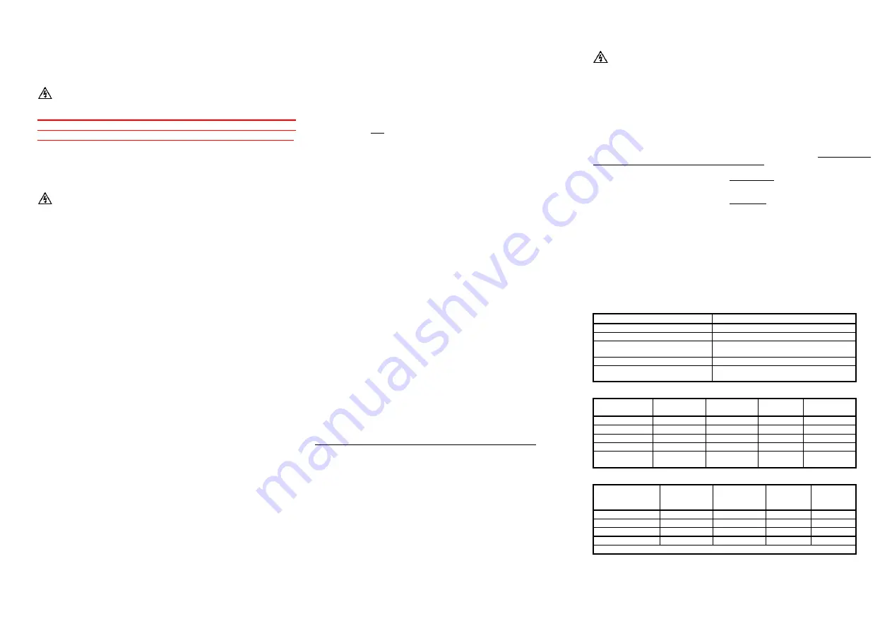
Colour Codes Around the World
Phase
IEC Colour
Code
Aus/NZ
Colour Code
US Color
Code
Canadian
Color Code
L1
(A)
Brown
Red
Black
Red
L2
(B)
Black
White
Red
Black
L3
(C)
Grey
Blue
Blue
Blue
N
(Neutral)
Blue
Black
White, grey
White
G
(Ground/Earth)
Yellow/Green
Stripe
Yell/Green
Stripe
Green,
Yell/Green
Green, bare
copper
Inputs and Connections on Various Systems
Colour and Input
Terminal
Single
Phase
(2-Wire)
Single
Phase
(3-Wire)
3 Phase
Delta
3 Phase
Wye/Star
Brown (L1/A1)
X (Live)
X (Live)
X (L1)
X (L1)
Black (L2/A2)
X (Earth)
X (L2)
X (L2)
Grey (L3/A3)
X (L3)
X (L3)
Blue (N)
X (Neutral)
X (Neutral)
X (N)
X (N)
For correct operation this recorder must have a proper Neutral (N) connection.