background image

ac

o

rn

c e i l i n g   f a n   s p e c i a l i s t

®

A�en�on:

This appliance is not intended for use by persons (including Children) 

with  reduced  physical,  sensory  or  mental  capabili�es  or  lack  of 

experience and knowledge unless they have been given supervision or 

instruc�on concerning use of the appliance by a person responsible for 

their safety.  Children should be supervised to ensure that they do not 

play with the appliance.

Model:  DC-368 / DC-368H

Instruc�on Manual

Summary of Contents for DC-368

Page 1: ...reduced physical sensory or mental capabili es or lack of experience and knowledge unless they have been given supervision or instruc on concerning use of the appliance by a person responsible for their safety Children should be supervised to ensure that they do not play with the appliance Model DC 368 DC 368H Instruc on Manual ...

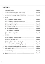
Page 2: ...ng Fan Wiring of Ceiling Fan Installa on of Canopy Installa on of Fan Blades Installa on of Lightkit 368H Installa on of Hanging Plate Pre fix the Ceiling Fan Wiring Installa on of Ceiling Fan Remote Control Manual Wiring Diagram Remote Control Manual Bu on Func on Maintenance Tips Troubleshoo ng Notes Page 2 Page 3 Page 4 Page 5 Page 5 Page 6 Page 7 Page 8 Page 8 Page 9 Page 9 Page 10 Page 10 Page...

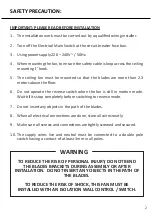
Page 3: ...ely before switching to reverse mode Do not insert any objects in the path of the blades When all electrical connec ons are done store all wires neatly Make sure all screws and connec ons are ghtly screwed and secured The supply wires live and neutral must be connected to a double pole switch having a contact of at least 3mm in all poles 1 2 3 4 5 6 7 8 9 10 IMPORTANT PLEASE READ BEFORE INSTALLATI...

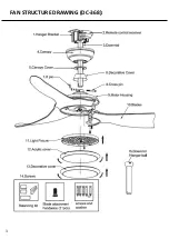
Page 4: ...FAN STRUCTURE DRAWING DC 368 3 ...

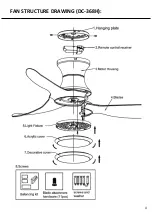
Page 5: ...FAN STRUCTURE DRAWING DC 368H 4 ...

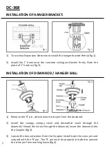
Page 6: ...the wires through the downrod insert the downrod into the Coupler fig 3 Loosen the two setscrews from the Coupler Install back the cross pin and secured with the R pin The R pin must be properly installed to prevent the cross pin from working loose fig 4 1 2 3 To use four Expansion Setscrew to install the hanger bracket firmly fig 1 Install the J hook onto the concrete ceiling and fasten firmly Note th...

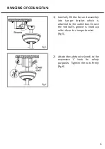
Page 7: ...nger bracket which is a ached to the outlet box Ensure the rod ball s groove is lined up with tab on the hanger bracket fig 5 A ach the safety wire cord to the expansion J hook for safety purposes Tighten the nuts firmly fig 6 1 2 HANGING OF CEILING FAN 6 ...

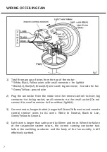
Page 8: ...onnector to the small socket Do not connect the small connector for fan without lightkit Connect motor hanger bracket hanger ball Green Yellow wires and remote control receiver wires to AC wires White to Neutral Black to Live Green Yellow to Ground Earth wire is longer than safety cord by 60mm and more When the failure of the suspension system occurs the current carrying conductor taut before the ...

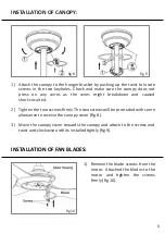
Page 9: ...d Tighten the two screws firmly The two screws will be protruded with some allowance to receive the canopy cover fig 8 Move the canopy cover towards the canopy and a ach to the screws and twist an clockwise un l its installed ghtly fig 9 1 2 3 Remove the blade screws from the motor A ached the blades to the motor and ghten the screws firmly fig 10 1 INSTALLATION OF FAN BLADES INSTALLATION OF CANOPY fig ...

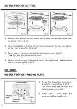
Page 10: ...plug in the wire to the lightkit docking connector fig 12 skip this step if using decora ve cover A ach the acrylic cover decora ve cover to the lightkit and twist clockwise un l its secured ghtly fig 13 1 2 3 4 To use four Expansion Setscrew to install the Hanging Plate fig 14 AC wires must pass through the hanging plate center hole Install the J hook onto the concrete and fastened firmly 1 2 INSTALL...

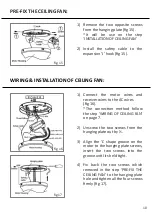
Page 11: ...the AC wires fig 16 The connec on method follow the step WIRING OF CEILING FAN on page 7 Unscrew the two screws from the hanging plate out by Align the L shape groove on the motor to the hanging plate screws insert the two screws into the groove un l its held ght Fix back the two screws which removed in the step PRE FIX THE CEILING FAN to the hanging plate hole and ghten all the four screws firmly fi...

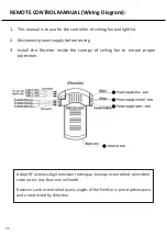
Page 12: ...upply before wiring Install the Receiver inside the canopy of ceiling fan to ensure proper protec on 1 2 3 Adopt RF wireless digit emission technique biunique controlled coincident code rate is less than one millionth Receiver can be controlled by any angles of the Emi er in prescrip ve space and unrestricted by direc on 11 ...

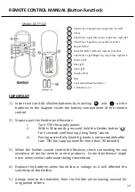
Page 13: ...ery compartment of the remote control Steps to pair the Emi er and Receiver i Turn ON the supply power ii Within 30 seconds press and hold the Emi er bu on for 5 seconds un l hearing a long beep sound iii Pairing successfully learning mode is not acceptable a er turn ON the supply power for more than 30 seconds When the Emi er cannot control the Receiver check surrounding for any existence of simi...

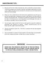
Page 14: ...of discolora on or tarnishing which would damage the motor or the wood or possibly cause an electric shock You can apply a light coat of furniture varnishing to the wood for addi onal protec on and enhance its beauty Surface scratched mark can be touch up with a light coat of shoe polish There is no need to oil your fan The motor is created with lubricated sealed ball bearings User are advised to ...

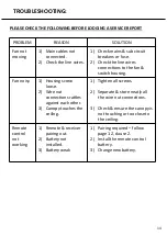
Page 15: ...ch housing Fan noisy 1 Housing screw loose 2 Wire nut connec ons ra les against each other 3 Canopy touches the ceiling 1 Tighten all screws 2 Separate store neatly all the wire nut connec ons 3 Check ensure the canopy is not touching or too close to the ceiling Remote control not working 1 Remote receiver pairing out 2 Ba ery not installed 3 Ba ery weak 1 Pairing required follow page 12 clause 2 ...

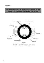
Page 16: ...NOTES DRAWING SHOWING THE ASSEMBLY OF WIRES THROUGH FAN MOTOR SHAFT FOR DECORATIVE CEILING FAN 15 ...

Reviews: