

- 1 -
User's Manual: Series 461A
Model 461A AC-Powered Alarm
Table of Contents
Page
Introduction..........................................................................
1
Description...........................................................................
1
Specifications.......................................................................
2
Installation............................................................................
4
Calibration............................................................................
5
General Maintenance...........................................................
6
List of Drawings
Page
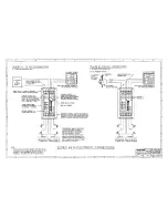
Electrical Connections (4501-542).......................................
7
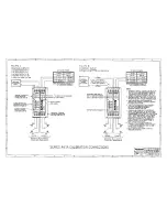
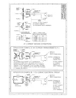
Calibration Connections (4501-543)....................................
8
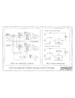
Simplified Schematic & Contact Protection (4501-544).......
9
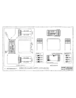
Configuration Jumper Location (4501-545)..........................
10
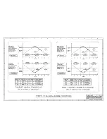
Failsafe/Non-Failsafe Alarm Conditions (4501-539)............
11
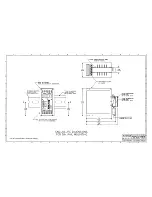
Dimensions: DIN Rail Mounting (4501-540)........................
12
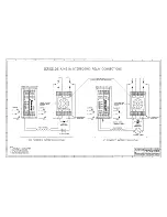
Interposing Relay Connections (4501-541)..........................
13
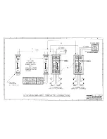
Alarm / Two-Wire Transmitter Connections (4501-547)......
14
AC Sensor Connections (4501-546)....................................
15
IMPORTANT SAFETY CONSIDERATIONS
It is very important for the user to consider the possible adverse
effects of power, wiring, component, sensor, or software failures in
designing any type of control or monitoring system. This is
especially important where economic property loss or human life is
involved. It is important that the user employ satisfactory overall
system design. It is agreed between the Buyer and Acromag, that
this is the Buyer's responsibility.
Acromag, Inc. Tel: (248) 624-1541
30765 South Wixom Road FAX: (248) 624-9234
P.O. Box 437
Wixom, Michigan 48393-7037, USA
Copyright 1995 Acromag, Inc., Printed in the USA.
Data and specifications are subject to change without notice.
8500-546-A95H000
INTRODUCTION:
These instructions cover the model types listed in Table 1
below. Supplementary sheets are attached for units with special
options or features.
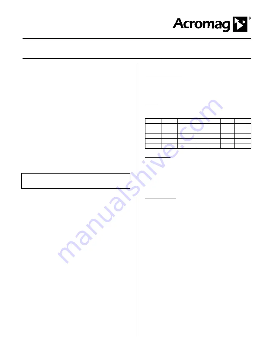
Table 1: A. Model Number Format:
461A-Input-Output-Power-Mounting-Cert-Calib
B. Typical Model Number: 461A-V5-SMRN-1-DIN-NCR
Series
Input
Output
Pwr
Mtg
Cert.
Calib.
461A
-V1
-SMRN
-1
-DIN
-NCR
Blank
-V5
-DMRN
-2
-C
-V0
-V50
-V100
Notes (Table 1):
1. The Alarm can be ordered with or without the factory calibration
("-C") option. Consult the selection and ordering guide for more
information. Any customer-specified calibration information will
be included on a separate calibration label on the unit.
2. Consult the factory for current information on agency (e.g.
Canadian Standards Association, etc.) approvals.
DESCRIPTION:
The Series 461A is an AC-powered, DIN-rail mounted alarm
family that accepts either a process current, or DC voltage input
signal, and provides single or dual alarm output relay contacts. The
Series 461A complements an entire family of Acromag flat-pack,
DIN-rail transmitters, alarms, and isolators, each designed to be
used as functional components that provide the user with a modular
solution for a wide range of field applications. The safe, compact,
rugged, and reliable design of this alarm allows it to be utilized in
either control room or field locations.
The electromechanical relay output provides one SPDT (Form
C) relay contact output (single alarm), or two SPDT (Form C) relay
contact outputs (dual alarm). The unit can be configured as a HIGH
or LOW single alarm, or a HIGH/HIGH, HIGH/LOW, LOW/HIGH or
LOW/LOW dual alarm. The operating mode of each relay can be
set to Failsafe (Normally Energized), or Non-Failsafe (Normally De-
Energized). The term 'Failsafe' refers to the condition that the relay
is energized during normal conditions, and de-energized upon alarm
or power loss to the unit. The Non-Failsafe mode of operation is
primarly used for simple control applications and acts opposite the
Failsafe mode--that is, the relay is
energized
during alarm
conditions.
Each channel has one pair of LED's (Green and Red) that
provide a visual indication of the alarm condition on the front of the
unit. When the Green LED is ON, it indicates a Normal condition,
and when the Red LED is ON, it indicates an Alarm condition. This
applies to both the Failsafe or Non-Failsafe operating mode. Thus,
line power status is simply indicated by an illuminated LED.


