background image

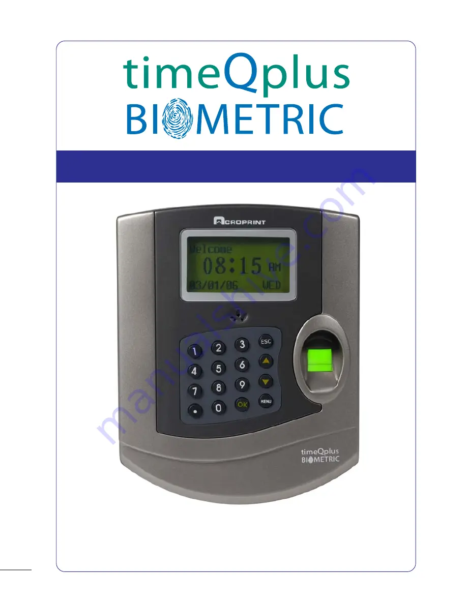
BIOMETRIC FINGERPRINT TECHNOLOGY

TQ100 Terminal User Manual

NOTE: This equipment has been tested and found to comply with the limits for a Class B digital
device, pursuant to Part 15 of the FCC Rules. These limits are designed to provide reasonable
protection against harmful interference in a residential installation. This equipment generates,
uses and can radiate radio frequency energy and, if not installed and used in accordance with
the instructions, may cause harmful interference to radio communications. However, there is
no guarantee that interference will not occur in a particular installation.  If this equipment does
cause harmful interference to radio or television reception, which can be determined by turning
the equipment off and on, the user is encouraged to try to correct the interference by one or
more of the following measures:  Reorient or relocate the receiving antenna; Increase the
separation between the equipment and receiver; Connect the equipment into an outlet on a
circuit different from that to which the receiver is connected; Consult the dealer or an
experienced radio/TV technician for help.
                                                                                                         PN:  06-0349-000 Rev C.

44         

      timeQplus BIOMETRIC

 Terminal User Manual

FIREWALL INFORMATION

Attention Microsoft Windows XP and Windows 2003 Users!

Microsoft Windows Firewall:

Microsoft has included firewall protection on Windows XP with Service Pack

2 and on Windows 2003 Server with Service Pack 1. If you will be installing

your timeQplus BIOMETRIC server on either of these two operating

systems you will need to grant access on the firewall to the following

applications and services after your installation is complete.

•   

Attendance Rx   Note: You will be prompted to unblock this

application after the installation is complete, or you can grant
access via the firewall.

•   

 arxsvc.exe

•   

 ARXTQ100N.exe

•   File and Printer Sharing

Other Firewalls:

Some firewalls block ports, and authorized applications can be granted

access to use specific ports. If you have this type of firewall you should

open the following ports:

•   

TCP

Open ports 49183 to 49188

•   

UDP

Open ports 49211 to 49212

Summary of Contents for TQ100 Terminal

Page 1: ...BIOMETRIC FINGERPRINT TECHNOLOGY TQ100 Terminal User Manual gital ble s th s es ing Pack alling anted hould ...

Page 2: ...43 ...

Page 3: ...ion Options 4 2 1 RS232 Serial Communication 4 2 2 RS485 Network Communication 4 2 3 Ethernet Communication Chapter Five Fingerprint Registration Enrollment 5 1 Enrollment Method 5 2 Fingerprint Registration Chapter Six Terminal Usage and Punching In Out 6 1 Successful validation when punching In Out 6 2 Unsuccessful validation when punching In Out Chapter Seven Administrator Functions 7 1 Data Ma...

Page 4: ...41 ...

Page 5: ...nal to the mounting plate D Plug in the power supply and turn the terminal on Press button 2 2 Keyboard image and functions Keypad configuration is presented in Figure 2 1 Figure 2 1 The keypad functionality is described below 1 2 3 ESC 4 5 6 7 8 9 0 OK MENU To perform EXIT CANCEL IGNORE when using the menu To access the Menu structure To confirm and save the selection Power switch Scroll up butto...

Page 6: ...39 RJ11 s to he d the should e andard ...

Page 7: ...vel 2 menu and browse through the seven items available Some of the items have corresponding sub items the level 3 menu as shown below Data Management User Registration Administrator Registration Sensitivity Level Setting Delete Registration Data View Punches View Admin Record Delete All Records Fingerprint Password Fingerprint or Password Sensitivity User Setting Global Setting ...

Page 8: ...ace 85 37 ...

Page 9: ...layed Press OK in each menu to display the corresponding item as follows Level 1 Menu Level 2 Menu Level 2 Menu System Info Total Punches Fingerprint Registration User of users Administrator of Administrators Password Admin Recs Admin Recs Press OK Press OK Press OK Note When User is selected pressing OK switches between User and Admin The other items work in a similar way d ords ...

Page 10: ...35 e ...

Page 11: ...serial cable included in your package connect one end to your PC communication serial port and the other end to TQ100 terminal E Power on the PC then the terminal Note RS232 is used to directly connect one terminal per computer In this case default setting is recommended For network configurations using multiple terminals the device ID number must not be repeated and must be set to different numbe...

Page 12: ...33 3 teway es PC be bps 0bps 0bps ...

Page 13: ...ayed as follows B Set the IP address subnet mask and default gateway to those of the LAN The IP address must be unique The same password must be used both in the terminal setup and PC software C Turn the terminal off D Connect the network cable of the LAN to the RJ45 interface of the terminal E Turn on the terminal n es Communication Default gateway RS485 Ethernet No Yes Note A 6 ft Ethernet cable...

Page 14: ...31 ws t ow ue is d ...

Page 15: ...timeQplus BIOMETRIC Terminal User Manual 15 Correct Not flat Off center Tilted Too Low The correct finger positioning method is illustrated below front and side view ...

Page 16: ...29 n ...

Page 17: ... digits located at the beginning of the number sequence are not required to key in Example If the user ID number is 0050 the user needs to key in only 50 Accept the user ID displayed or key in a user ID and press OK to display the following Finger New Enroll No ESC Yes OK New Enroll ID 00001 ESC Set OK Note ID range can be any combination of numbers from 00001 65535 New Enroll Place Finger 1 l d d...

Page 18: ...27 lay rint ...

Page 19: ...be redone and or a different finger used Next the screen is displayed and a new enrollment cycle begins as shown below Press OK to continue enrolling new users press ESC to enroll backup multiple fingerprints for a user Fig D If you want to enroll fingerprint backups for existing users enter the user ID number of the employee you want to add fingerprint backups for For password registration an exp...

Page 20: ...25 e t ord g ...

Page 21: ...er will hear a vocal message saying Please try again The message displayed will show Refer to Chapter Five to ensure that the correct fingerprint method is used B When the password validation is used If the password validation fails the user will hear a vocal message saying Please try again the following message is displayed FP Check Failed Try again PW Check Enter again mpts he ...

Page 22: ...face ete ds 23 ...

Page 23: ...n Administrator registration Sensitivity level setting Delete registration data View punches View admin record and Delete all records 7 1 1 Select User registration menu and then press OK to enter the level 3 menu as follows Select fingerprint registration and then press OK refer to Chapter Five for fingerprint enrollment Select password registration and press OK to display the following User Fing...

Page 24: ...21 ed ...

Page 25: ...es that the machine accepts the fingerprint of user A as the identity of user B while FRR means that the machine rejects a fingerprint that has been enrolled Global setting value is based on the sensitivity level value of all the users while User setting value is based on the sensitivity level value of each individual In general use Global setting value based on all users can be set default value ...

Page 26: ...19 ...

Page 27: ...owing Note C 00001 total number of punches is 1 N 00001 indicates the latest record 05 05 20 02 45 validation time V_F indicates registration type is fingerprint The interface displays the total number of punches validated with fingerprint the detailed time of each occurrence punch user registration number and type of each validation ViewPunch ID 00000 ESC Confirm OK ViewPunch C 00001 N 00001 05 0...

Page 28: ...17 s ay ...

Page 29: ...ion Record E_DP Delete Password Registration Record D_L Delete All Record Data S_T Time Setting S_S System Setting S_L Record Setting S_C Communication Setting 7 2 Setup Press MENU to enter and select Setup menu Then press OK to access the level 2 menu with the following display The Setup menu consists of System Setting Record Setting Communication Setting and Display Adjustment Setting 7 2 1 Syst...

Page 30: ...15 ...

Page 31: ...Interval setting defaulted as per below Record ARecAlert 100 PRecAlert 1000 DupPunches No Setting Items Explanation No 1 255 Factory Setting 1 Admin Record Alert The terminal will not give out an alert when the admin records have overflowed If the admin records surpass the maximum storage capacity then the terminal will not store any new admin records The maximum storage capacity for administrator...

Page 32: ...13 ion ws ...

Page 33: ... 1 Device ID machine number Setting Items Explanation 1 255 To set the ID number for machines Factory Setting 1 Note Machine number is the unique ID for each machine If there are two machines with the same machine number in the network they will not work properly and the PC software will be confused when polling the terminals Unique ID numbers need to be allocated for network use 2 Baud Rate Setti...

Page 34: ...11 d to ...

Page 35: ...way of the LAN when using the Ethernet communication 192 168 1 1 Note The default gateway must be consistent to the LAN settings Setting Items Explanation Yes Factory Setting 8 RS485 Communication Setting Items Explanation Yes Factory Setting 9 Ethernet Make the Ethernet communication available Yes Make the RS485 communication available No ...

Page 36: ...9 u s ...

Page 37: ...guide function with 9 pins in total Definitions of each pin are listed in the following table PIN Definition 1 Reserved 2 RS232 TX 3 RS232 RX 4 LOCK Data 1 5 GND 6 Reserved 7 Data 8 Reserved 9 Reserved timeQplus BIOMETRIC Terminal User Manual 37 RS232 Communication Diagram Note For door access and or access control applications connect with the pins four and five when using the simple entrance gua...

Page 38: ...u 7 ...

Page 39: ...king at the RJ11 connector see the RS485 wiring diagram below the Brown wire goes to the leftmost pin The Brown White wire goes to the rightmost pin of the RJ11 connector 3 Connect the cable above one end at the RJ45 Interface of terminal and the RJ11 connector to a Junction Box the Black wire in the Junction Box should go to the Brown 8 wire in the CAT5 cable and the Yellow wire in the Junction B...

Page 40: ...5 n lds ...

Page 41: ...timeQplus BIOMETRIC Terminal User Manual 41 user the to ss e and Ethernet Communication Diagram ...

Page 42: ...3 t t ...

Page 43: ...timeQplus BIOMETRIC Terminal User Manual 43 ...

Page 44: ......

Reviews: