


Quick Guide P/N: 220010481-G Ver: 100-004
AMB-VDX3H1 Series
Acrosser Technology Co., Ltd.
1
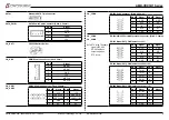
Top View
CN_COM3
CN_COM4
CN_PWR1
CN_FPIO1
CN_COM2
CN_USB2
CN_USB1
CN_KM1
JP_GP1
CN_GP1
CN_GP2
SATA_PWR1
SATA1
SW_COM3
SW_COM4
JP_I2C1
CN2
CN1
CN_BAT1
1
1
1
1
1
1
1
1
1
1
CN_I2C1
SoC
1
JP_IDE2
IDE1
1
1
1
1
Bottom View
CF1
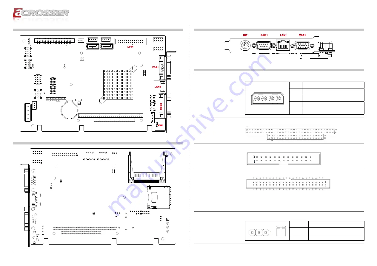
IO View
Connector and Jumper Pin Definition
CN_PWR1
ATX Power Input
Pin #
Signal
1
+5V (4A)
2
GND
3
GND
4
+12V (1.2A)
CN1
CN2
Standard PC/104 Module Connector
LPT1
Standard Parallel 26-pin Connector
IDE1
Standard IDE 44-pin Connector
PS: Pin 41, 42: +5V/1.5A max
Note:
The jumper selection of HDD,SSD or ODD should be
“Master”.
JP_IDE2
IDE1 Vcc Jumper Setting: (Pitch: 2.54mm)
Short
Function
1-2
+5V / 1.5A (default for HDD)
2-3
+3.3V / 1.5A


