background image

August 2004

PTC Dampers

Actionair

Installation and Operating Instructions

Smoke/Shield PTC, Vent/Shield PTC,
Hot/Shield PTC, Smoke/Shield PTC, and
Hot/Shield Vent PTC are all trademarks
of Actionair.

Smoke/Shield PTC 
Modes 5 and 6 shown.

Hot/Shield PTC 
Modes 5 and 6 shown.

Index

Heath and Safety.
General Information.
PTC Damper Installation.

2

Smoke/Shield PTC 
Mode 1 Installation.

3

Smoke/Shield PTC and
Vent/Shield PTC
Modes 5 and 6 Installation.

3

Smoke/Shield PTC and 
Vent/Shield PTC Control 
Modes Dimensional Data.

4

Smoke/Shield PTC and
Vent/Shield PTC
Application and Wiring.

5

Hot/Shield PTC and 
Hot/Shield Vent PTC
Damper Installation and
Dimensional Data.
Application and Wiring.

6

Hot/Shield PTC and 
Hot/Shield Vent PTC
Dimensional Data.

7

Hot/Shield PTC and 
Hot/Shield Vent PTC
Multiple Assembles

7

Smoke/Shield PTC, 
Vent/Shield PTC, 
Hot/Shield PTC and
Hot/Shield Vent PTC
Troubleshooting.

8

(Smoke/Shield PTC™ Modes 1,5 & 6
fail-safe spring close with manual or
electrical reset).

(Vent/Shield PTC™ Modes 5 & 6 fail-
safe spring open with manual or
electrical reset).

(Hot/Shield PTC™ Modes 5 & 6 are
operational up to 300 °C for 1 hour
with fail-safe spring closure).

(Hot/Shield Vent PTC™ are
operational up to 300 °C for 1 hour
with fail-safe spring opening).

Smoke/Shield PTC, Vent/Shield PTC, 

Hot/Shield PTC, and Hot/Shield Vent PTC 

Summary of Contents for Smoke/Shield PTC

Page 1: ...lication and Wiring 5 Hot Shield PTC and Hot Shield Vent PTC Damper Installation and Dimensional Data Application and Wiring 6 Hot Shield PTC and Hot Shield Vent PTC Dimensional Data 7 Hot Shield PTC and Hot Shield Vent PTC Multiple Assembles 7 Smoke Shield PTC Vent Shield PTC Hot Shield PTC and Hot Shield Vent PTC Troubleshooting 8 Smoke Shield PTC Modes 1 5 6 fail safe spring close with manual o...

Page 2: ...tallation frames are delivered to site as a complete assembly with the appropriate PTC damper fitted therein The damper shall be installed centrally in the thickness of a brickwork or concrete surrounding wall or floor or in the case of thick walls or floors so that the centre line of the frame is at least 50mm but not more than 75mm away from the nearest face of the wall or floor in which the ass...

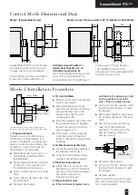
Page 3: ... Three position 180 Pivotable Control Mode Control Mode Dimensional Data 2 Fit Control Mode Remove transit plate from damper shroud and discard Slide the interface and mode assembly into the shroud having ensured that the slots in the interface case and the drive coupling are in line Push the assembly fully home until the spring retaining pin engages through the location hole in the shroud snaploc...

Page 4: ...ess installations the ETR should be fitted onto the damper spigot not casing above the damper shroud and in accordance with these fitting instructions The damper should be manually reset and released using the winder provided to ensure that correct mechanical operation is achievable It is possible to mechanically lock open the Smoke Shield PTC damper to allow air to pass through it by using the wi...

Page 5: ...s Connect 24V via a safety isolating transformer Vent Shield PTC dampers and associated control modes 5 and 6 are reverse acting with spring action opening Mode 6 230V System Power On Damper motors open Power Off Spring closure or via Electrical Thermal Release External mechanical position indicator with pointer Release Time 16 secs Reset Time 1c secs To isolate from main power supply the system m...

Page 6: ...urposes Please contact our Customer Service Office for details when incorporating thickened fire rated ductwork 411 421 161 27 191 Damper Installation and Control Mode Fitting Series 2501 Hot Shield PTC Application and Wiring 1 2 1 2 3 4 VOLT FREE CONTACT CLOSED WHEN DAMPER RELEASED VOLT FREE CONTACT CLOSED WHEN DAMPER RESET A C D C 24V 50 60 Hz 10 V A 7 2 W 30 50 C CONTINUOUS A C 250V 6 3 A SUPPL...

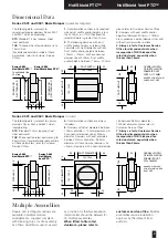
Page 7: ...mpers with duct diameters between 100mm diameter 150mm diameter will have nominal damper size of 200mm diameter Dampers with duct diameters between 151mm diameter 982mm diameter will have nominal damper size 50mm Dampers with a nominal damper size between 983mm diameter 1000mm diameter please refer to Customer Service Office 7 Always refer to Customer Service Office for dimensional data when incor...

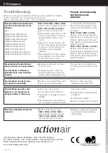
Page 8: ...rrectly wired The ETL cables have been damaged or tampered with Control Mode operates but limited or no movement of damper blades is observed The mode is not correctly synchronised with the interface The damper is damaged or poorly installed The retaining pin in the interface is not protruding through the location hole in the shroud Foreign matter is impeding blade movement Location plate omitted ...

Reviews:

Related manuals for Smoke/Shield PTC