
IMPORTANT NOTE:
Please read this manual carefully before installing or operating your new air conditioning unit and keep it available for future
reference.
That’s better. That’s Actron.
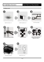
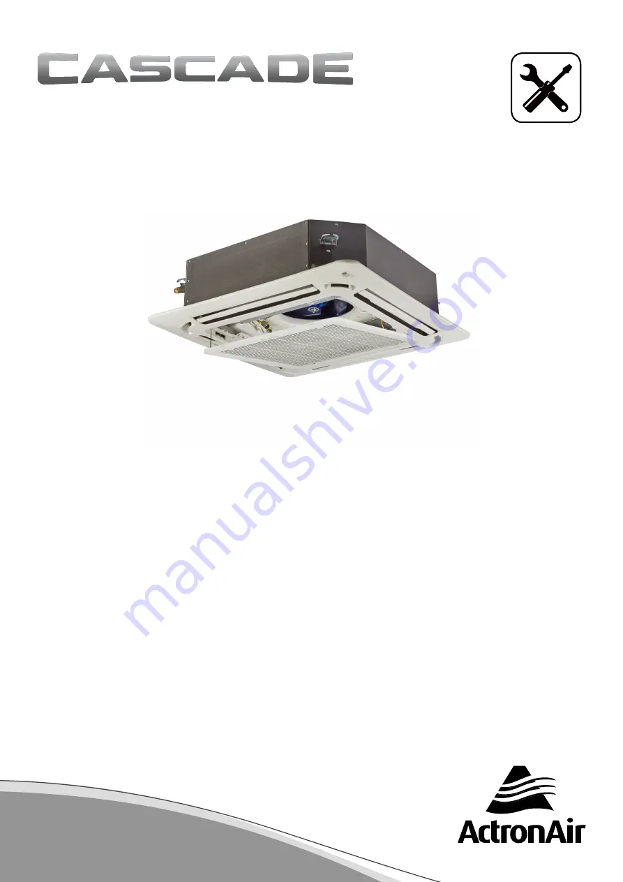
INSTALLATION MANUAL
Model Numbers:
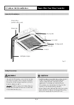
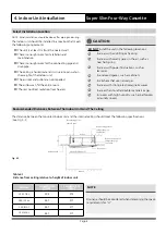
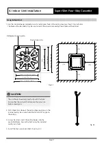
Super Slim Four-Way Cassette
URC-071AS / CRE-071AS
URC-100AS / CRE-100AS
URC-125AS / CRE-125AS
URC-140AS / CRE-140AS
That’s better. That’s Actron.
Summary of Contents for Cascade CRE-071AS
Page 39: ...Page 39 ...


