background image

This document is copyright and is supplied Internally in strict confidence. It must not be
reproduced nor shown to third parties either in part or in its entirety without ACURA’s 
written consent.


L-A210 User manual 


Document Reference:  L-A210 V1.6 Serial Reader User Manual 


Date: 19

th 

March   2012 

Summary of Contents for Wavetrend IPSU

Page 1: ...ternally in strict confidence It must not be reproduced nor shown to third parties either in part or in its entirety without ACURA s written consent L A210 User manual Document Reference L A210 V1 6 S...

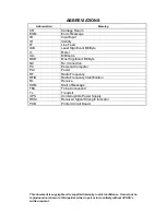
Page 2: ...CR Carriage Return EOM End of Message I O Input Input ID Identity LF Line Feed LSB Least Significant Bit Byte m Meter mm Millimetre MSB Most Significant Bit Byte NC No Connection PC Personal Computer...

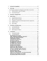
Page 3: ...es 18 6 Commands 20 6 1 Command shortlist 20 6 2 Command Details 21 Reset Network Command 21 Start Enabling Polling Mode Command 21 Disable Auto Polling Command 22 Ping Reader Command 22 Set Network I...

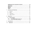
Page 4: ...0 Status 31 7 Interfaces and Connections 32 7 1 Interfaces 32 7 2 RS232 32 7 3 Connections 33 7 4 USB Connection 33 8 Diagnostics 34 8 1 Diagnostic LEDS 34 8 1 1 Normal Mode 34 8 1 2 Auto Poll Mode Ma...

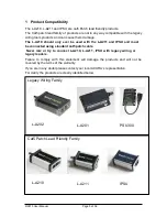
Page 5: ...the L A211 and IPSU and must be connected using standard cat5 patch cable Never mix or try to connect L A210 L A211 IPSU with legacy wiring or legacy readers Failure to comply with this statement will...

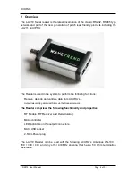
Page 6: ...the following functions Receive decode and validate data from ACURA s L Output relevant tag data via USB or via the Reader Network The Reader comprises the following functionality and properties RF Mo...

Page 7: ...1 have a larger buffer size of 9 tags compared to the L A201 which was 5 Tags RJ45 Connection In the event that a user connected up an L A201 incorrectly there was a high chance that the damage could...

Page 8: ...MI and ESD noise Connection to the USB port is made via a standard USB mini type B plug It should be noted that the operation of the RS232 port is controlled by software and the default setting for al...

Page 9: ...orts USB RS232 and RS485 allowing it power up to 8 readers over RS485 Dependent on cable lengths In order to power longer cable runs with more readers an IPSU can be added in line to provide extra pow...

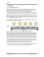
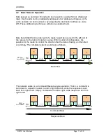
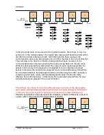
Page 10: ...or 2 wire RS485 2 wire RS485 2 wire RS485 2 wire 2 wire RS485 RS485 Power Data Flow Power is also carried to each reader on the cable running between them Since each RS485 connection between readers...

Page 11: ...vice versa With this kind of configuration it is possible for the reader to control the direction that the data is flowing and handle it accordingly The complete network would look as follows 1 2 3 4...

Page 12: ...ER ID is therefore to allow a consistent and permanent address assignment to each reader Logically one would use NODE ID addresses in a command packet to assign a READER ID to a specific reader NODE I...

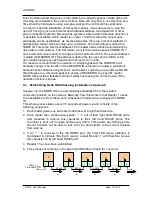
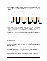
Page 13: ...network assignment 9 There is now a further 1 second delay before the whole network is now ready and active Reader 1 actually waits a further 2 seconds after its 500ms timeout before it becomes activ...

Page 14: ...ch reader assembles the packet in its memory for analysis when completed Once a complete command packet is received the contents are analysed for errors and addressing Should this be a Command packet...

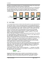
Page 15: ...polling routines Where no tag data is available an empty reply packet will be sent back This enables the monitoring software to determine if there are any readers on the network that are not respondi...

Page 16: ...ser Manual Page 16 of 35 Auto Polling sequences start with a complete system communications reset to ensure that the network is seen correctly This happens each time the auto polling is switched on ev...

Page 17: ...Response Packets 0x5 Data Network Receiver Node Command Data Checksum All bytes are HEX values 9 Header 1 Byte 0x55 10 Length 1 Byte Number of Bytes in data section 11 Network ID 1 Byte 12 Receiver I...

Page 18: ...nly use the remaining addresses to determine the reader being addressed If a value of 255 is placed into any of these addresses it is an indication to the reader that this command is being broadcast t...

Page 19: ...5 on the network Reader ID address is ignored 1 0 0 Invalid will have no response 1 4 0 Access Reader with Reader ID 4 on Network 1 1 0 123 Access Reader 123 on the Network 1 255 12 0 Access all Read...

Page 20: ...lue Reply Packet RSSI 0x08 Set RSSI Value Reply Packet 0x09 Set Site Code Reply Packet 0x0A Get Site Code Reply Packet Site Code 0x0B Set Receiver Gain Reply Packet 0x0C Get Receiver Gain Reply Packet...

Page 21: ...sequence It sets the Auto Polling flag in the Data EEPROM to enable Auto Polling after power up It will establish the size of the network by sending out tag requests until such time that it gets no re...

Page 22: ...can be addressed directly to reader 1 or on a broadcast basis Command 0xA 0x00 Network Receiver Node ID 0x02 Checksum Response 0x5 0x00 Network Receiver Node ID 0x02 Checksum Ping Reader Command The...

Page 23: ...rk Receiver Node ID 0x05 Checksum Get Tag Packet Command This will be the most used command on any system Its function to request a Tag from the reader if there is one ready for sending A tag is remov...

Page 24: ...ent switch counter 10 Age byte MSB 11 Age byte 12 Age byte 13 Age byte LSB 14 Site code MSB 15 Site code 16 Site code LSB 17 Tag ID MSB 18 Tag ID 19 Tag ID 20 Tag ID LSB 21 Type of tag flag 22 Reader...

Page 25: ...ecksum Response 0X5 0x01 Network Receiver Node ID 0x08 RSSI Checksum Set Site Code Command The Site Code or Site Code is a group of 3 bytes assigned to each tag Its function is to enable the reader to...

Page 26: ...ksum Response 0x5 0x0 Network Receiver Node 0x0 Gain Checksum Gain 0 Low Gain Mode Short range reader Gain 1 High Gain Mode Long range reader Set Alarm Tag Filter Status Command This command will filt...

Page 27: ...t this reader It is a single byte and represents the power in 0 1 voltage increments Eg Value 131 13 1 Volts Returns the voltage that the reader is receiving via either its RJ45 ports or via the 2 5mm...

Page 28: ...d Rate It will only accept a broadcast command and there is no response sent Changes are immediate will result in communications loss if the PC does not change its baud rate accordingly Command 0xA 0x...

Page 29: ...reader will receive standard L series tag packets and will generate Null tag packets in the event that no tags are within range Null packets are empty tag packets that some Legacy software uses as a...

Page 30: ...bytes Longitude 4 bytes User Data 10 bytes Response 0x55 0x00 Network ID Reader ID Node ID 0xF0 Checksum Get Info Returns the Set Info settings as well as the following values Model number 1 byte 1 L...

Page 31: ...Network Voltage 1 byte Not used 21 bytes Protocol 1 byte 0 legacy 1 no nulls 2 L Plus Controller Firmware Version 1 byte RF Module Firmware Version 1 byte Controller Hardware Version 1 byte RF Module...

Page 32: ...top 1 Data Bits 8 7 2 RS232 The Default setting for RS232 is ON in the event that it has been turned off the reader must be first connected up using either 485 or the USB port This functionality is su...

Page 33: ...ough 5 Straight Through 6 Gnd 6 Gnd 7 RS485 7 RS485 8 RS485 8 RS485 Please Note that unless RS232 has been turned ON its default is OFF Standard Cat 5 cabling must be used for connecting the L A210 7...

Page 34: ...ction Tag RX Orang Valid Tag received from the RF Module System Green Indicates that the system communications are Idle and OK 8 1 2 Auto Poll Mode Master reader only Poll Orang Successful Poll of cur...

Page 35: ...it Colour Material Connections 105 mm x 58mm x 28mm 118 grams Aluminium Grey Aluminium 2 x RJ45 socket 1 Mini USB type socket 2 5mm Power socket Radio Frequency Receive Frequency Modulation Sensitivit...

Page 36: ...r 25 MHz 4 GHz EN55022 Radiated emissions 30 MHz 1 GHz EN55022 Conducted emissions 150 kHz 30 EN61000 4 3 Radiated immunity 80 MHz 1 GHz excl 433 92 MHz 20 MHz EN61000 4 4 Electrical fast transients E...

Reviews: