background image


 DIN EN ISO 9001:2000 

 certified 


ADDI-DATA GmbH

Dieselstraße 3


D-77833 OTTERSWEIER


Technical support:


+49 (0)7223 / 9493 – 0


Technical description 


MSX-E1701  


Intelligent Ethernet 

counter/digital I/O module 


- Digital I/O -  


Edition: 01.02 – 04/2007

Summary of Contents for MSX-E1701

Page 1: ...1 2000 certified ADDI DATA GmbH Dieselstraße 3 D 77833 OTTERSWEIER Technical support 49 0 7223 9493 0 Technical description MSX E1701 Intelligent Ethernet counter digital I O module Digital I O Edition 01 02 04 2007 ...

Page 2: ...nly is protected by copyright Duplication of the information contained in the operating instructions and of any other product information or disclosure of this information for use by third parties is not permitted unless this right has been granted by the product licence issued Non compliance with this could lead to civil and criminal proceedings ADDI DATA software product licence Please read this...

Page 3: ...afety precautions yellow leaflet If this leaflet is not with the documentation please contact us and ask for it Observe the instructions of the manual Make sure that you do not forget or skip any step We are not liable for damages resulting from a wrong use of the product Used symbols i IMPORTANT designates hints and other useful information WARNING It designates a possibly dangerous situation If ...

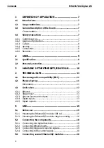
Page 4: ... DATA 11 4 1 Electromagnetic compatibility EMC 11 4 2 Physical set up 11 Dimensions 11 4 3 Limit values 12 4 3 1 Ethernet 12 4 3 2 Trigger input 13 4 3 3 Synchro inputs and outputs 13 4 3 4 Digital inputs 13 4 3 5 Digital outputs 14 5 USE 15 5 1 Before use 15 5 1 1 Mounting the Ethernet I O module DIN rail 15 5 1 2 Mounting the Ethernet I O module Angle mounting 16 5 2 Connecting the components 18...

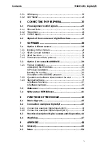
Page 5: ...ccess with ADDIPACK 30 7 2 1 Module registration 30 a Assigning the IP address 30 b Module registration 30 Inserting the module 30 Description of the ADDIREG program 34 7 2 2 Questions and software downloads on the web 35 7 2 3 Standard software 37 a Software functions 37 b Software samples 39 7 3 Webserver 40 7 4 Software tool SETMSXExxxx 41 8 FUNCTIONS OF THE MODULE 45 8 1 Block diagram 45 8 2 C...

Page 6: ...nals MSX E1701 25 Fig 7 1 SOAP in the TCP IP protocol staple 28 Fig 7 2 Board type list 31 Fig 7 3 Settings 31 Fig 7 4 Settings OK 32 Fig 7 5 Settings not OK 32 Fig 7 6 ADDIREG main window example 33 Fig 7 7 ADDevice Manager 33 Fig 7 8 Board clear insert 35 Fig 7 9 SET MSX Exxx Main menu 41 Fig 7 10 New IP address changed 44 Fig 8 1 Block diagram 45 Fig 8 2 Connection example Digital inputs 24 V 4...

Page 7: ...plosive atmospheres 1 3 General description of the board Characteristics The Ethernet I O module MSX E1701 can be used for the acquisition of incremental counter inputs and the processing of digital signals via 16 digital inputs outputs 1 4 Safety precautions 1 4 1 Current sources All connected devices must be supplied from current sources that comply with SELV according to IEC 60950 or EN 60950 o...

Page 8: ... Accessories table 1 4 6 Remarks The use of the Ethernet I O module according to its intended purpose includes observing all advices given in this manual and in the safety leaflet Uses beyond these specifications are not allowed The manufacturer is not liable for any damages which would result from the non observance of this clause Make sure that the Ethernet I O module remains in its protective p...

Page 9: ...rained in electronics are entitled to perform the following works installation use maintenance 2 2 Personal protection Consider the country specific regulations about the prevention of accidents electrical and mechanical installations radio interference suppression 9 ...

Page 10: ...andling of the Ethernet I O module MSX E1701 Digital I O 3 HANDLING OF THE ETHERNET I O MODULE Fig 3 1 Correct handling Do not touch the connectors Hold the module only at the sides and at the bottom 10 ...

Page 11: ...x Height L x W x H MSX E1701 215 mm x 110 mm x 54 mm Fig 4 1 Dimensions Weight MSX E1701 900g 960 g with DIN rail mounting Degree of protection Degree of protection IP 651 Versions Digital I O Counter2 MSX E1701 24 V RS422 MSX E1701 24 24 V 24 V 1Please observe that the protection is only reached if adequate protection caps are used see chapter Fehler Verweisquelle konnte nicht gefunden werden 2 T...

Page 12: ...ty features Optical isolation 1000 V Voltage reversal protection max 1 A Current supply Nominal voltage 24 V direct current symbol acc to IEC 60417 5031 Supply voltage 18 30 V Current consumption at 24 V 150 mA 10 Degree of protection Degree of protection IP 654 4 3 1 Ethernet Number of ports 2 3 Not contained in the standard delivery 4 Please observe that the protection can be reached only if ade...

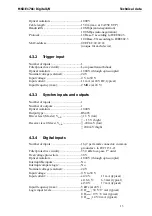
Page 13: ... Synchro inputs and outputs Number of inputs 1 Number of outputs 1 Optical isolation 1000 V Output type RS485 Driver level Master VA B 1 5 V low 1 5 V high Receiver level Slave VA B 200 mV low 200 mV high 4 3 4 Digital inputs Number of inputs 16 2 per female connector common ground acc to IEC 1131 2 Filter protective circuitry 33 9 kHz low pass 1st order Overvoltage protection 30 V Optical isolati...

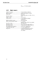
Page 14: ...Current max 1 85 A typical at 8 channels through PTC Output current per output 500 mA typical Short circuit current per output 1 7 A max Shutdown logic at 24 V Rload 10mΩ RDS ON resistance 280 mΩ max Switching on time 100 μs max RL 48Ω of 80 Vout Switching off time 150 μs max RL 48Ω of 10 Vout Overtemperature shutdown 135 C max output driver Temperature hysteresis 15 C typ output driver Diagnostic...

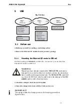
Page 15: ...ule to a DIN rail WARNING Should you have already mounted the MSX E1701 and want to transport it in a switch cabinet or in other systems do ensure that there is sufficient transportation lock The MSX E1701 could fall e g from the DIN rail which could lead to the damage of the I O module and or other objects persons Attach the clamps to the Ethernet I O module Fasten the clamps in the holes with th...

Page 16: ...et MX Screw see PDF table Accessories you can prepare the Ethernet I O module for the direct attachment to machines and devices According to your requirements you can attach the four angles either pointing inside or outside Fig 5 3 Angles pointing to the outside Fig 5 4 Angles pointing to the inside For mounting please observe the following steps Unscrew the screws from the side of the Ethernet I ...

Page 17: ...into the opening Put the angle on the seal Fasten the angle with a short screw from the mounting set Fig 5 6 Angle mounting After having attached the angles to the Ethernet I O module you can attach the module directly to devices and machines with further screws 17 ...

Page 18: ...e yourself Take the Ethernet I O module out of its protective pack 5 2 1 Connecting the digital functions Select one or more plugs for digital functions CH0 CH15 Digital plugs Fig 5 7 Selecting a digital plug Plug the function cable clamp into the required plug s 18 ...

Page 19: ...le in Ethernet port 05 Fig 5 8 Connecting Ethernet ports 5 2 3 Connecting trigger and synchro signals Plug the cable into the plug Trigger Sync In1 Fig 5 9 Connecting trigger and synchro signals 5 If you want to connect several Ethernet I O modules please do observe chapter 5 3 19 ...

Page 20: ...nt supply 5 3 Connecting several Ethernet I O modules You can connect several Ethernet I O modules Hereto please observe the following steps Connect the first Ethernet I O module as described above Connect the components as shown in the figure see next page 6 If you want to connect several Ethernet I O modules please do observe chapter 5 3 ...

Page 21: ...21 Fig 5 11 Connecting several Ethernet I O modules Use MSX E1701 Digital I O ...

Page 22: ...tus LED lights green the module is ready for work Lights yellow If the Status LED lights yellow the network cables are possibly not connected Status Detailed description of the Status LED See table next page Fig 5 13 LEDs Digital I O Direction State LED Description Ouput inactive black No output is active there is no voltage Output active red Output is active there is voltage Caution short circuit...

Page 23: ...inks see LEDs Port 0 ACT LINK and Port 1 ACT 1 LINK Please observe that in the meantime also further errors can occur that prevent data acquisition e g a short circuit Blinks red yellow System still works and communicates correctly but dangers are possible to arrive Internal temperature is low LOW or high HIGH The module should be handled appropriately Lights yellow System is serviceable but canno...

Page 24: ...are not working correctly The Flash memory is not working correctly A wrong IP address has been configured Check your IP address Contact us for reparation or exchange Blinks green System is working Firmware update Data acquisition is running Lights green System is ready for work Note During booting the LED Status is yellow 24 ...

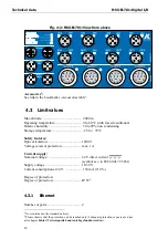
Page 25: ...of the function signals see chapter 6 2 6 1 Pin assignment control signals Fig 6 1 Control signals MSX E1701 6 1 1 Ethernet Ports Table 6 1 Pin assignment Ethernet Port 0 and Port 1 Ethernet Port 0 Ethernet Port 1 Pin No Ethernet female connector D coded M12 Ethernet female connector D coded M12 1 TD0 TD1 2 RD0 RD1 3 TD0 TD1 4 RD0 RD1 Ethernet Port 0 Ethernet Port 1 25 ...

Page 26: ...chro trigger output Blue 4 Synchro trigger input Synchro trigger output Black 5 Ground Ground Gray Trigger Sync In Trigger Sync Out Photo Connecting the trigger synchro signals see Fig 5 9 6 1 3 Current supply Table 6 3 Pin assignment Current supply Power Input Power Output Cable color Pin No Male connector 5 pin M12 Female connector 5 pin M12 1 24 V 24 V Brown 2 24 V 24 V Whiter 3 Ground Ground B...

Page 27: ...ed double and that the assignment of the digital I O is determined on the female connector n via 2n and 2n 1 0 n 7 Examples n 0 Digital I O 2x0 0 and 2x0 1 1 on female connector 0 n 3 Digital I O 2x3 6 and 2x3 1 7 on female connector 3 n 7 Digital I O 2x7 14 and 2x7 1 15 on female connector 7 Pin No Female connector 5 pin M12 Cable color 1 24 V Brown 2 Digital I O 2n 1 White 3 Ground Blue 4 Digita...

Page 28: ...ition MSX E1701 server access information SOAP server Port number 5555 Data server Port number 8989 7 1 2 SOAP General definition What is SOAP SOAP originally Simple Object Access Protocol is a protocol with which data can be exchanged between systems and Remote Procedure Calls can be executed SOAP is based on services of other standards XML for representing the data and internet protocols of the ...

Page 29: ...a server and data protocol What is a data server A data server is a network component that reads data from the module and sends it to all clients Characteristics Multiclients Optimized for high throughput and fast servicing of available data Data protocol A data package consists of five fields field format 32 bit little indian time stamp low time stamp high source counter source type data Time sta...

Page 30: ... when the index comes 7 2 Option 2 Access with ADDIPACK 7 2 1 Module registration a Assigning the IP address Install and start SETMSXExxxx is on the delivered CD Change the IP address of the Ethernet I O module more information see chapter Fehler Verweisquelle konnte nicht gefunden werden software tool SETMSXExxx b Module registration Install ADDIPACK is on CD1 standard drivers After this continue...

Page 31: ...isplayed Fig 7 2 Board type list Click on OK After this the following window appears Fig 7 3 Settings Select the network card under Ethernet interface Make sure that you have selected the network card to which the Ethernet I O module is connected Enter the IP address or 31 ...

Page 32: ...ed the SOAP connections will be checked After the scan has been completed successfully and no errors have been detected during the check of the SOAP connections the OK button will be activated and your settings will be listed under Module information Fig 7 4 Settings OK Fig 7 5 Settings not OK This window is displayed if your settings are OK You can continue as described below This window is displ...

Page 33: ...in ADDIPACK Starting the ADDevice Managers Click on Edit and then on ADDIDriver board manager After this the ADDevice Manager opens Fig 7 7 ADDevice Manager The ADDevice Manager shows the following information First column Module name Board Index Number allocated to the Ethernet I O module when registered in ADDIREG IP address Serial number 33 ...

Page 34: ...king twice within a column the connection principle and the technical data of the resource are displayed This function is only possible if a question mark appears with the cursor You can export the set configuration as a text file Click on file and save the configuration as a txt file with Export information to file Then you can print the configuration or use it for other boards Once you have cont...

Page 35: ... pleased to support you e mail info addi data de or hotline addi data de Free downloads of standard software You can download the latest version of the software for the Ethernet I O module MSX E1701 http www addi data com i IMPORTANT Before using the product or in case of malfunction during operation check if there is an update of the technical description or driver The current version can be foun...

Page 36: ...Software MSX E1701 Digital I O 36 ...

Page 37: ...DDIDATA_GetLastError i_ADDIDATA_GetLastErrorAndSource b_ADDIDATA_EnableErrorMessage b_ADDIDATA_DisableErrorMessage b_ADDIDATA_FormatErrorMessage b_ADDIDATA_GetNumberOfDigitalInputs Digital b_ADDIDATA_GetDigitalInputInformation inputs b_ADDIDATA_GetDigitalInputInformationEx b_ADDIDATA_Read1DigitalInput b_ADDIDATA_Read2DigitalInputs b_ADDIDATA_Read4DigitalInputs b_ADDIDATA_Read8DigitalInputs b_ADDID...

Page 38: ...alOutputsOn b_ADDIDATA_Set32DigitalOutputsOff b_ADDIDATA_Get1DigitalOutputStatus b_ADDIDATA_Get2DigitalOutputStatus b_ADDIDATA_Get4DigitalOutputStatus b_ADDIDATA_Get8DigitalOutputStatus b_ADDIDATA_Get16DigitalOutputStatus b_ADDIDATA_Get32DigitalOutputStatus Watchdog b_ADDIDATA_GetNumberOfWatchdogs b_ADDIDATA_GetWatchdogInformation b_ADDIDATA_GetWatchdogInformationEx b_ADDIDATA_InitWatchdog b_ADDID...

Page 39: ...gital outputs with without output memory option Give the status of the digital outputs if possible SAMPLE04 Test 8 digital outputs with without output memory option Give the status of the digital outputs if possible SAMPLE05 Test 16 digital outputs with without output memory option Give the status of the digital outputs if possible SAMPLE06 Test 32 digital outputs with without output memory option...

Page 40: ...er this the window Module information appears Abb 7 1 Webserver Module information Table 7 3 Webserver Further points Point Description Module information General information about the Ethernet I O module is displayed see figure above Security Change the default password mxadmin Please enter your new password twice Encryption of the webserver data possible TLS Digital I O Configuration of digital ...

Page 41: ...ditional information about the Ethernet module NTP client Remote synchronization of the Ethernet module by saving the IP address of the server on the module You have to set this only once Contact ADDI DATA contact information 7 4 Software tool SETMSXExxxx The software tool SETMSXExxxx supports you in Changing the IP address of the Ethernet I O module either via the current IP address or via the se...

Page 42: ... IP address of the module MSX E301x via the current IP address 6 Updating the MSX E301x firmware 7 Changing the IP address of the module MSX E351x via the serial number 8 Changing the IP address of the module MSX E351x via the current IP address 9 Updating the MSX E351x firmware e Exit Application sample Changing the IP address via the serial number of the analog input module MSX E3011 Firstly sca...

Page 43: ...ll connected modules Note the serial number of the selected module the serial number can be found on the label on the back of your module You will automatically get into the main menu Enter as Your selection the number9 1 4 or 7 The following window appears 9 1 MSX E170x 4 MSX E301x 7 MSX E350x 43 ...

Page 44: ...Digital I O Enter the serial number and the new IP address Firstly a Ping test is realized on the selected IP address to test whether it is occupied or not Then the new IP address is set Fig 7 10 New IP address changed 44 ...

Page 45: ...O Functions of the module 8 FUNCTIONS OF THE MODULE 8 1 Block diagram Fig 8 1 Block diagram 8 2 Connection examples Digital I O 8 2 1 Connection example Digital inputs 24 V Fig 8 2 Connection example Digital inputs 24 V 45 ...

Page 46: ...he I O configuration register The outputs that are configured as ports are highly ohmic now i IMPORTANT Per connector only both ports can be configured as input or output 2 Now put 24 V on the output by setting the corresponding bits on 1 in the digital output register 3 To control it you can read the set ports back in the digital input register 4 If there is a short circuit at the switched output...

Page 47: ... watchdog is activated 2 The watchdog counter is started with the Reload Value at each write access to the outputs At each write access to the outputs it is counted down newly with the reload value 3 If there is a watchdog underrun all digital outputs are set on 0 V an interrupt is generated the underrun bit is set the enable bit remains set 4 As long as the watchdog is in the underrun each write ...

Page 48: ...inter FIFO First In First Out The first data into the buffer is the first data out of the buffer Gain The factor by which an incoming signal is multiplied Input impedance The measured resistance and capacitance between the high and low inputs of a circuit Input level The input level is the logarithmic relation of two electric units of the same type voltage current or power at the signal input of a...

Page 49: ...ber to which a measurement can be determined For example a converter with 12 bit resolution can resolve 1 part in 4096 Sensor A device that responds to physical stimuli heat light sound pressure motion etc and produces a corresponding electrical output Throughput rate The maximum repetitive rate at which data conversion system can operate with a specified accuracy It is determined by summing the v...

Page 50: ...ic compatibility EMC 11 Ethernet Connecting 19 Limit values 12 F Functions of the board 44 G Glossary 47 H Handling of the Ethernet I O module 10 I Inserting the module 30 Intended use 7 Internet 35 IP address 31 L LED Status 23 Limit values 12 M Mounting Angle 16 DIN rail 15 P Personal protection User 9 Physical set up 11 Q Qualification User 9 R Registration 30 S Serial number 31 Settings 31 Sof...

Page 51: ...MSX E1701 Digital I O Appendix Watchdog W Funktionsbeschreibung 46 Weight 11 51 ...

Reviews: