background image

NetVanta 1531/1534/1544 Series

Hardware Installation Guide 

1700570F1

NetVanta 1531

1700571F1

NetVanta 1531P

1702590G1

NetVanta 1534

1702591G1/G2

NetVanta 1534P

1702544G1

NetVanta 1544

1702545G1/G2

NetVanta 1544P

1700546G1#120

NetVanta 1544F with 120 VAC Power Supply

1700546G1#240

NetVanta 1544F with 240 VAC Power Supply

1200884G1

Wall Mounting Bracket (NetVanta 1531/1534/1544 Series)

1700512F1

Dual Wall Mounting Bracket 

1700511F1

Rack Mounting Bracket (NetVanta 1531 Series)

1700508F1

19-inch Dual Mounting Tray

1700530F1

NetVanta 1131 RPS/EPS

1700532F1

NetVanta 1131 RPS Cable

1700533F1

NetVanta 1131 EPS Cable

1700534F1

NetVanta 1131 Dual Mounting Tray

61702590G1-34H
August 2019

Summary of Contents for 1200884G1

Page 1: ...with 120 VAC Power Supply 1700546G1 240 NetVanta 1544F with 240 VAC Power Supply 1200884G1 Wall Mounting Bracket NetVanta 1531 1534 1544 Series 1700512F1 Dual Wall Mounting Bracket 1700511F1 Rack Moun...

Page 2: ...lication Software Licensing Agreement Each ADTRAN product contains a single license for ADTRAN supplied software Pursuant to the Licensing Agreement you may a use the software on the purchased ADTRAN...

Page 3: ...yright 2019 ADTRAN Inc 3 Conventions Warnings provide information that could prevent injury or endangerment to human life Cautions signify information that could prevent service interruption or damage...

Page 4: ...ket outlet shall be installed near the equipment and shall be easily accessible If any of the following conditions occur unplug the product from the electrical outlet and replace the part or contact y...

Page 5: ...es applicables aux appareils num riques de Class A prescrites dans la norme sur le materiel brouilleur Appareils Num riques NMB 003 edictee par le ministre des Communications Toll Fraud Liability Be a...

Page 6: ...upplying Power to the Unit 37 Installing a CompactFlash Card 37 NetVanta 1131 RPS EPS 38 NetVanta 1131 Series Shipping Contents 38 NetVanta 1131 Front Panel Design 39 NetVanta 1131 Rear Panel Design 3...

Page 7: ...igure 12 NetVanta 1544P Rear Panel Layout 23 Figure 13 NetVanta 1544F Front Panel Layout 23 Figure 14 NetVanta 1544F Rear Panel Layout 24 Figure 15 NetVanta Rack Mounting Brackets and Kensington Lock...

Page 8: ...019 ADTRAN Inc 8 List of Tables Table 1 Front Panel LED Descriptions 25 Table 2 Front Panel LED Behaviors 40 Table A 1 CONSOLE Port Pinouts 47 Table A 2 1000Base T Gigabit Ethernet Port Pinouts 47 Tab...

Page 9: ...rovides installation instructions Physical Descriptions on page 10 Product Specifications on page 26 Unit Installation on page 29 NetVanta 1131 RPS EPS on page 38 For additional information on mountin...

Page 10: ...modules The SFP modules provide Gigabit Ethernet fiber connectivity for high speed uplinks or switch stacking For a list of supported SFP modules visit the ADTRAN website at http www adtran com Power...

Page 11: ...0Base T Ethernet Interfaces The front panel contains 10 10 100 1000Base T Ethernet interfaces RJ 45 These interfaces are arranged in stacked pairs with the numbers 1 through 10 screened from left to r...

Page 12: ...switch is located on the left side of the unit and is used to toggle Ports 1 through 8 between link activity and PoE display modes CONSOLE Interface The CONSOLE interface is an EIA 232 serial port DCE...

Page 13: ...EIA 232 CONSOLE port DB 9 is located on the rear panel The NetVanta 1534P is housed in a 1U high rack mountable metal enclosure that can be mounted in a standard 19 inch rack and includes a universal...

Page 14: ...s unit is shipped in its own cardboard shipping carton Open each carton carefully and avoid deep penetration into the carton with sharp objects After unpacking the unit inspect it for possible shippin...

Page 15: ...mode switch is located on the left side of the unit and is used to toggle Ports 1 through 28 between link activity and VCID display modes 10 100 1000Base T Ethernet Interfaces The front panel contains...

Page 16: ...on page 47 shows the connector pinouts NetVanta 1534P 25 26 27 28 1G 2 5G VCID PoE LINK ACT EPS RPS STAT 1 2 3 4 5 6 7 8 9 10 11 12 13 14 15 16 17 18 19 20 21 22 23 24 Figure 7 NetVanta 1534P Front Pa...

Page 17: ...ed pair of interfaces are located directly over the interfaces Refer to Table A 2 on page 47 for pinouts SFP Slots The front panel contains four industry standard SFP slots for fiber or copper connect...

Page 18: ...VAC or 240 VAC power supply The front panel contains 24 100 1000Base X SFP interfaces that are accessed via fiber or copper using industry standard SFP modules Four industry standard 1000 2500Base X...

Page 19: ...eries Shipping Contents Each NetVanta 1544 Series unit is shipped in its own cardboard shipping carton Open each carton carefully and avoid deep penetration into the carton with sharp objects After un...

Page 20: ...ed these LEDs will display VCID status future release Status LED The STAT LED is located on the left side of the unit and indicates the unit s status Redundant Power Supply LED The RPS LED is located...

Page 21: ...nector Refer to Table A 1 on page 47 for pinouts Connection directly to an external modem requires a cross over cable RPS The rear panel has a power input to a 12 VDC RPS The RPS LED located on the fr...

Page 22: ...is located on the left side of the unit and is used to toggle Ports 1 through 48 between link activity and VCID display modes CONSOLE Interface The CONSOLE interface is an EIA 232 serial port DCE tha...

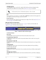
Page 23: ...wer input to the AC universal power supply Please refer to Supplying Power to the Unit on page 37 for connection details NetVanta 1544F Front Panel Design The NetVanta 1544F front panel is shown below...

Page 24: ...a 1544F front panel contains four 1000 2500Base X SFP interfaces These interfaces are numbered 25 through 28 and their status LEDs are located directly under these numbers Rear Panel Design The NetVan...

Page 25: ...een solid Link status activity is being displayed PoE PoE units only Off PoE status is not being displayed Green solid PoE status is being displayed VCID 1534 1534P 1544 1544P only Future Release Off...

Page 26: ...Vanta 1544 Nonblocking 8 k NetVanta 1534 or 16 k NetVanta 1531 1544 medium access control MAC addresses Maximum Forwarding Bandwidth NetVanta 1531 24 Gbps NetVanta 1534 62 Gbps NetVanta 1544 68 Gbps D...

Page 27: ...p to 24 NetVanta wireless access points WAPs Environment Operating Temperature 0 C to 50 C 32 F to 122 F Storage Temperature 20 C to 70 C 4 F to 158 F Relative Humidity Up to 95 percent noncondensing...

Page 28: ...ht 2019 ADTRAN Inc 61702590G1 34H Compliance FCC Part 15 Class A EN 55022 Class A EN 55024 EN 61000 3 2 EN 61000 3 3 ICES 003 Class A EN 300 386 AS NZS CISPR22 Class A UL CUL 60950 1 EN 60950 1 IEC 60...

Page 29: ...tricted access location as described in UL IEC 60950 1 Do not remove the cover on the RPS or EPS connectors on the rear of the unit These connectors are reserved for future use The NetVanta 1600 Serie...

Page 30: ...ries NetVanta 1534 and NetVanta 1544 can be rack mounted with two units side by side using the optional dual mounting tray P N 1700508F1 The following steps guide you in mounting the NetVanta into a r...

Page 31: ...s 1U of space 4 Have an assistant hold the unit in position as you install two mounting bolts through the unit s brackets and into the equipment rack using a 2 Phillips head screwdriver 5 Apply power...

Page 32: ...4 Insert the provided screws through the tabs into the NetVanta units securing them with a screwdriver 5 Apply power to the units refer to Supplying Power to the Unit on page 37 The NetVanta 1531 1531...

Page 33: ...arately For instructions on wall mounting a single NetVanta 1531 1531P 1534 1534P 1544 refer to the instructions and Figure 17 on page 34 For instructions on dual wall mounting the NetVanta 1531 1531P...

Page 34: ...tud using 6 to 10 2 5 inch or greater in length wood screws Important Mounting to a stud ensures stability Using sheetrock anchors may not provide sufficient long term stability 4 Have an assistant ho...

Page 35: ...lity Using sheetrock anchors may not provide sufficient long term stability 4 Have an assistant hold the units in position as you install two 6 to 10 wood screws 1 inch or greater in length through th...

Page 36: ...ter in length wood screws Important Mounting to a stud ensures stability Using sheetrock anchors may not provide sufficient long term stability 4 Have an assistant hold the unit in position as you ins...

Page 37: ...cords are shipped with the units To power these units connect the power cable to an appropriate AC power source Installing a CompactFlash Card The CompactFlash slot NetVanta 1544F only supports any in...

Page 38: ...ounted rack mounted singly using the provided rackmount brackets or rack mounted two side by side using the optional dual mounting tray P N 1700534F1 The NetVanta 1131 and the NetVanta switch with whi...

Page 39: ...EPS is functioning RPS Alarm LED The RPS ALM LED is located on the left side of the unit and indicates whether the RPS is functioning Fan Alarm LED The FAN ALM LED is located on the left side of the u...

Page 40: ...sed separately LED Behaviors Table 2 Front Panel LED Behaviors Power Off The unit is not receiving power Green solid The unit is receiving power RPS ALM Off The RPS is functioning properly Red solid T...

Page 41: ...tible with the maximum specified 50 C ambient temperature Installation of the equipment in a rack should be such that the amount of air flow required for safe operation of the equipment is not comprom...

Page 42: ...supplied with the unit 2 To allow proper grounding scrape the paint from the rack around the mounting holes where the unit will be positioned 3 Position the unit in a stationary equipment rack either...

Page 43: ...nits side by side on the dual mounting tray lining up the holes in the front of the units with the holes in the tabs on the front of the tray see Figure 24 Important To avoid damaging the unit when at...

Page 44: ...el so that the LEDs are visible 3 Prepare the mounting surface by attaching a board typically plywood 3 4 inch to 1 inch thick to a wall stud using 6 to 10 2 5 inch or greater in length wood screws Im...

Page 45: ...r until the pins are fully inserted and the base of the connector is flush with the unit Important Do not use excessive force If the connector does not insert easily check to ensure you are inserting...

Page 46: ...panel of the unit 4 Connect the other end 3 prong plug of the unit s power cord to the proper 110 to 240 VAC grounded receptacle Your NetVanta unit is now ready to be configured and connected to the n...

Page 47: ...minal Ready input 5 SG Signal Ground 6 DSR Data Set Ready Tied to pin 1 output 7 Unused 8 CTS Clear to Send Tied to pin 1 output 9 Unused Table A 2 1000Base T Gigabit Ethernet Port Pinouts 1 TRD0 Tran...

Page 48: ...T 12 RX_DAT 3 TX_DISABLE 13 RX_DAT 4 I2C_SDA 14 GND 5 I2C_SCL 15 VddR 6 MOD_DEF 0 16 VddT 7 RATESEL 17 GND 8 RX_LOS 18 TX_DAT 9 GND 19 TX_DAT 10 GND 20 GND NetVanta 1531 1534 1544 Series 48 Copyright...

Reviews: