

ATLAS 550 (DC SYSTEM)
P/N 1200550L2
For more detailed documentation, visit us online at
Quick Start Guide
Quick Start Guide, 61200550L2-13A, June 2003
Technical Support 1-888-4ADTRAN (1-888-423-8726)
2003 ADTRAN, All Rights Reserved
Connecting to the ATLAS 550
To access the terminal menus and management features of the ATLAS 550,
connect the unit to a VT100 terminal (or VT100 terminal emulator) via the
C
RAFT
interface on the front panel or the
A
DMIN
interface on the rear panel.
Perform Steps Below in the Order Listed:
1. Configure a VT100 terminal (or terminal emulation software) with the
following settings:
If the terminal has a parallel setting, disable it and use serial.
2. Connect an appropriate cable into the ATLAS 550
C
RAFT
or
A
DMIN
port, and
connect to the VT100 terminal.
3. Initiate a terminal session and the
L
OGIN
screen displays. The default
password is
password
. (Passwords in the ATLAS 550 are case sensitive.)
Data Rate:
9600 baud
Data Bits:
8
Parity Bits:
None
Stop Bits:
1
Flow Control:
None
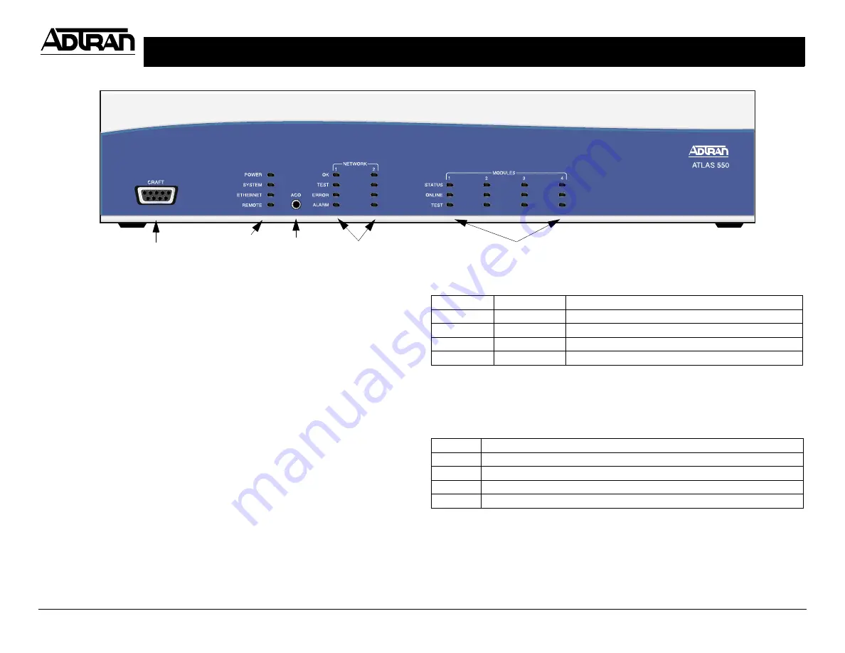
Network
Module LEDs
Option Module LEDs
Craft Interface
ACO
Switch
Craft Pinout
System Status LEDs
The System Status LEDs display the status of the power supply, controller, and
other system conditions for the ATLAS 550. For a more detailed discussion of
the front panel LEDs, refer to Section 2,
Engineering Guidelines
, of the ATLAS
550 System Manual.
PIN
NAME
DESCRIPTION
1, 4, 6-9
N/A
Not Connected
2
RD
Receive Data (output)
3
TD
Transmit Data (input)
5
SG
Signal Ground
LED
Description
Power
Indicates the status of the power supply.
System
Indicates the status of the unit controller and other system conditions.
Ethernet
Indicates the status of the Ethernet port.
Remote
Indicates whether a user (Telnet or VT100) is logged in to the unit.
Reviewing the Front Panel
System Status
LEDs


