
ESU 120E
P/N 1200420L1
For more detailed documentation, visit us online at
www.adtran.com
Quick Start Guide
Quick Start Guide, 61200420L1-13A, January 2003
Technical Support 1-888-4ADTRAN (1-888-423-8726)
Copyright
2003 ADTRAN, All Rights Reserved
N
ETWORK
C
ONNECTION
P
INOUT
Pin
Name
Description
1
TX DATA
Transmit data towards the Network
2, 4, 5, 7
GROUND
Frame Ground
3
RX DATA
Receive data from the Network
6, 8, 10, 12-15
UNUSED
—
9
TX DATA
Transmit data towards the Network
11
RX DATA
Receive data from the Network
PBX
DTE Device
VT 100 Terminal or
device running SLIP
or async PPP protocol
Module Expansion Slot
E1 or FE1
(75
W
Connectors)
(120
W
Connector)
Network
I
NSTALLATION
I
NFORMATION
•
A 120
Ω
DB-15 interface or two 75
Ω
BNC connectors for transmit and receive
(labeled
NETWORK
) are provided to connect to the network T1 circuit. The
pinout is provided on this Quick Start Guide. See
Chapter 2, Installation,
of the
ESU 120e User Manual for more information.
•
The rear panel contains a single DB-25 Nx 56/64 interface for connecting to
DTE equipment and a G.703 interface for a PBX. The pinouts for these
interfaces are located in
Appendix C
of the ESU 120e User Manual.
•
The ESU 120e provides a single option module expansion slot for use with
available ESU 120e modules including Nx 56/64 V.35, Nx 56/64 530,
Dual Nx 56/64 V.35, Nx DBU, and Router Modules. For more information on the
supported modules, refer to
Chapter 1
of the ESU 120e User Manual.
•
When shipped from the factory, the ESU 120e is uninitialized and set to factory
default conditions. At the first application of power, the unit will automatically
execute self-tests followed by an initialization sequence.
•
The ESU 120e can be configured and controlled using the local front panel of
the unit or from ADTRAN’s PC Control Program, T-Watch PRO™. A limited
menu tree is provided on the back of this sheet. For more detailed menu
information, refer to the ESU 120e User Manual.
•
Additional information can be found on the product CD which contains the
ESU 120e User Manual and Data Sheets.
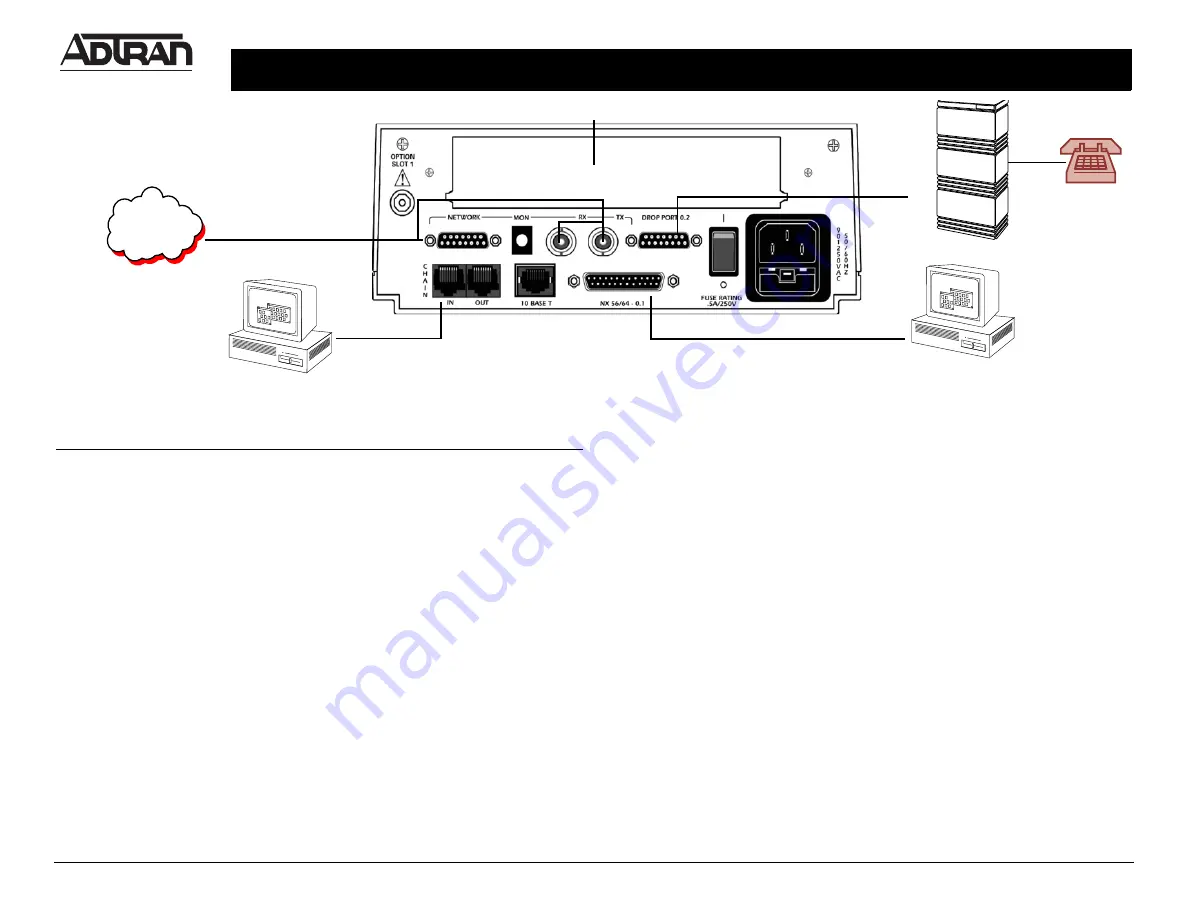
R
EAR
P
ANEL
D
ESCRIPTIONS
Network Connector
Connection to E1 or FE1 circuit (DB-15 or BNC)
Test Interface
Bantam jack provided for monitoring and testing
Control In/Out
Connection to a VT100 terminal
Nx 56/64 Connector
High-speed DTE interface
Module Slot
For use with available ESU 120e option modules
Power Switch
Turns power to the ESU 120e on or off
Power Connection
Power cord IEC connection for a reliably grounded
90-240 VAC, 50-60 Hz power source


