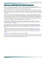
background image

Total Access 3000 
Hi-Cap RT Solution 
Installation and Maintenance Manual

Document Number: 64192MB3K2LX-1B
October 2007

®

Summary of Contents for Total Access 3000

Page 1: ...Total Access 3000 Hi Cap RT Solution Installation and Maintenance Manual Document Number 64192MB3K2LX 1B October 2007...

Page 2: ...lder of this Document The contents of this document are current as of the date of publication ADTRAN reserves the right to change the contents without prior notice In no event will ADTRAN be liable fo...

Page 3: ...er documentation and is also used for emphasis This font indicates on screen messages and prompts This font indicates text to be typed exactly as shown This font indicates silk screen labels or other...

Page 4: ...rviews on product features and functions while covering applications of ADTRAN product lines ADTRAN provides a variety of training options including customized training and courses taught at our facil...

Page 5: ...Arrangement 7 Installation 11 Mounting the Cabinet 11 Shipping Container 11 Transportation and Storage 11 Concrete Pad Location and Construction 12 Pad Layout 12 Cabinet Mounting Template 12 Lifting...

Page 6: ...s A 1 ADTRAN Technical Support A 1 ADTRAN Repair CAPS A 1 Repair and Return Address A 1 Figures Figure 1 Equipment Chamber 3 Figure 2 End Chamber 4 Figure 3 Hi Cap RT Solution Diagram 8 Tables Table 1...

Page 7: ...s The major components of the Hi Cap RT Solution include the following Emerson MESA Bridge Cabinet AC Load Center 120 VAC GFI Convenience Outlet Intrusion Alert Switches Environmental Control Card ECC...

Page 8: ...he following pages for the physical layout of the cabinet Table 1 Component Documentation Component Document Number Total Access 3000 3010 System Manual 61181001L1 1 Total Access 3000 23 Inch Chassis...

Page 9: ...er Tray with 23 Inch Fan Module Assembly Total Access 3000 Shelves Figure 1 Equipment Chamber MON OUT OUT IN MON IN MON OUT OUT IN MON IN P OW ER VALERE O N L I N E CUST O UT CUST IN CUST MON NTWK O U...

Page 10: ...MS2 splice modules ECC A divider panel separates the End Chamber from the Equipment Chamber The divider panel has wire pass through openings and also supports the components within the End Chamber Ben...

Page 11: ...e cabinet The ECC monitors thermistor input heat exchanger fans and ECC alarm outputs for high temperature intrusion and system failures For more information on the ECC refer to Section 6 Environmenta...

Page 12: ...y the customer Refer to Battery Installation on page 17 for battery installation information Total Access 3000 Hi Cap RT Solution The Hi Cap RT Solution uses the Total Access 3000 as the backbone for...

Page 13: ...ons 57 through 100 are not connected Loop 2 pairs are wired sequentially to positions 101 through 156 Positions 157 through 200 are not connected The customer is responsible for making the wire wrap j...

Page 14: ...OUT NT WK I N NT WK MON Customer Supplied DS3 Feed DS3 Protection Chassis DS3 1 DS3 2 DS3 NIUS Chassis 28 X DS1 HDSL or T1 RS 485 Total Access 3000 Shelf 1 200 Pair Cross Connect Equipment Side 112 U...

Page 15: ...30 Loop 2 TX 102 130 Slot 3 Loop 1 RX 3 31 Loop 2 TX 103 131 Slot 4 Loop 1 RX 4 32 Loop 2 TX 104 132 Slot 5 Loop 1 RX 5 33 Loop 2 TX 105 133 Slot 6 Loop 1 RX 6 34 Loop 2 TX 106 134 Slot 7 Loop 1 RX 7...

Page 16: ...Slot 21 Loop 1 RX 21 49 Loop 2 TX 121 149 Slot 22 Loop 1 RX 22 50 Loop 2 TX 122 150 Slot 23 Loop 1 RX 23 51 Loop 2 TX 123 151 Slot 24 Loop 1 RX 24 52 Loop 2 TX 124 152 Slot 25 Loop 1 RX 25 53 Loop 2 T...

Page 17: ...g and storing the cabinet to a staging or installation site Refer to local safety procedures and the appropriate Emerson cabinet documentation Shipping Container The cabinet should not be transported...

Page 18: ...ly by Emerson The template must be installed in the concrete foundation pad The template orients the mounting bolts and provides access to conduits in the pad The Pad Mount Template Kit ADTRAN P N 335...

Page 19: ...ure the vertical channel to the pole and lag screws and washers that secure the top stabilizers to the pole are customer provided Refer to Section 2 8 Pole mounting with standard pole mount kit in Eme...

Page 20: ...ling AC power ensure that the AC ground system is installed The ground system must be in compliance with local practices and building codes For detailed installation and wiring instructions of the AC...

Page 21: ...efer to Section 3 AC Power Emerson document 631 205 071 The Hi Cap RT Solution cabinet accepts a separately protected 120 VAC single phase 60 Hz circuit Load sizes breakers vary from 10 amps to 30 amp...

Page 22: ...return bus TB1 terminals are euro style with a supply and return terminal for each load Total Access 3000 Shelf 1 and Shelf 2 and the Total Access 23 Inch Fan Module Assembly have redundant power capa...

Page 23: ...tery installation arrangement and wiring Cabinet design includes an isolated and vented Battery Chamber beneath the Equipment Chamber The Hi Cap RT Solution requires one string of batteries A battery...

Page 24: ...ndition WARNING All grounds must terminate at a known ground source Ensure metal to metal contact on all ground connections Do not group or stack connections Verify ground circuit continuity To instal...

Page 25: ...ter cable sheath 9 inches above the upper cone shaped sleeve Remove the entire sheath above the ring cut 3 Ring cut the cable ground shield at the same place as the outer sheath Remove the entire grou...

Page 26: ...up the Valere Power System Rectifier complete the following steps 1 Ensure that all DC breakers are OFF before applying AC power to the PS R DC circuit breakers are located in the Valere DC distributi...

Page 27: ...procedures for the DS3 MUX These prerequisites have been performed in the systems integration process of the cabinets These procedures include the following Installation and wiring of Total Access 300...

Page 28: ...g connections are used to report alarms to network Alarming connections are to be cross connected as needed and noted on the Alarm Block label Table 8 Alarm Block Terminations Reporting Alarming Total...

Page 29: ...Block A protection module is provided for the corresponding position in the Protector Block After a cross connect has been completed the HDSLx or appropriate technology module should then be seated in...

Page 30: ...the failed fuse ADTRAN does not recommend that repairs be attempted in the field Repair services may be obtained by returning the defective unit to ADTRAN Refer to Appendix A Warranty for further info...

Page 31: ...es support Customer and Product Service CAPS requests or further information ADTRAN Sales Pricing Availability 800 827 0807 ADTRAN Technical Support Pre Sales Applications Post Sales Technical Assista...

Page 32: ...Carrier Networks Division 901 Explorer Blvd Huntsville AL 35806...

Reviews: