background image

Terra

TM

  3700B

SERVICE MANUAL

Advance model: 908 4203 010

146 1965 000(2)2007-02

Summary of Contents for Terra 3700B

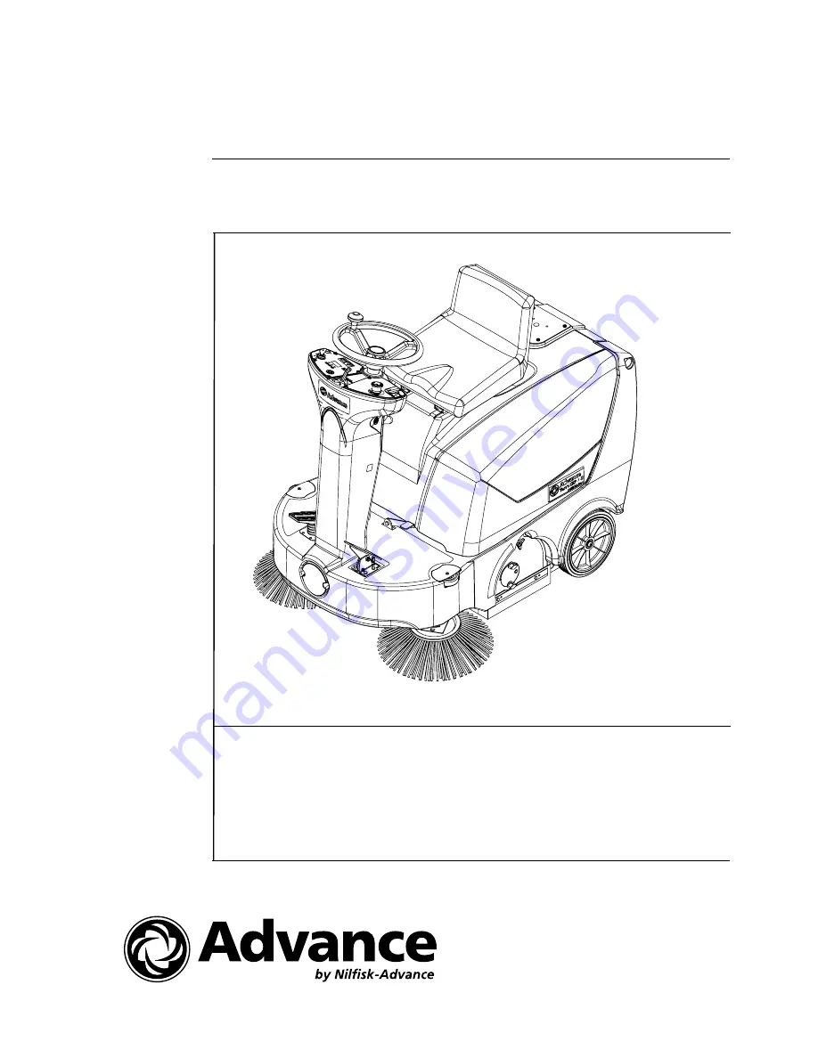
Page 1: ...TerraTM 3700B SERVICE MANUAL Advance model 908 4203 010 146 1965 000 2 2007 02...

Page 2: ...ENGLISH SERVICE MANUAL 146 1965 000 2 2007 02 TerraTM 3700B...

Page 3: ...BON BRUSH CHECK AND REPLACEMENT 19 MAIN MOTOR AND REDUCTION UNIT REMOVAL INSTALLATION 20 STARTER DYNAMO AND REDUCTION UNIT REMOVAL INSTALLATION 22 SIDE BROOM MOTOR ELECTRICAL INPUT CHECK 24 SIDE BROOM...

Page 4: ...USTMENT 47 TROUBLESHOOTING 48 OTHER SYSTEMS 49 SCREW AND NUT TIGHTENING CHECK 49 FRONT COVER DISASSEMBLY ASSEMBLY for machines from serial number 062211247 50 STEERING COLUMN TILTING ADJUSTING LEVER R...

Page 5: ...rm Number 146 1964 000 TerraTM 3700B Battery Charger Kit Nilfisk Form Number 146 2055 000 TerraTM 3700B Manual Vacuum System Kit Nilfisk Form Number 146 2049 000 TerraTM 3700B Working light Kit Nilfis...

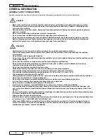
Page 6: ...th corrosive substances Do not use compressed air to clean this type of machine Do not use the machine in particularly dusty areas While using this machine take care not to cause damage to people and...

Page 7: ...7 x 1 97 in 200 x 50 mm Rear wheels 9 84 x 1 97 in 250 x 50 mm Machine total weight 317 5 lb 144 kg without batteries Forward speed 5 5 km h Reverse speed 4 4 km h Gradeability 16 Hopper capacity 9 5...

Page 8: ...aintenance procedures see the following paragraphs SCHEDULED MAINTENANCE TABLE Maintenance operation Upon delivery Every 10 hours Every 50 hours Every 100 hours Every 200 hours Every 400 hours Battery...

Page 9: ...s on fixed axle Front driving and steering wheel Right side broom Left side broom Main broom Left side skirt Right side skirt Front skirt Rear skirt Hopper Hopper hook Hopper handle Main broom left li...

Page 10: ...000 2 2007 02 TerraTM 3700B MACHINE NOMENCLATURE for machines up to serial number 062211246 14 1 16 3 4 5 2 9 6 7 15 13 12 10 22 23b 23a 44 46 18 20 49 19 17 47 25 21 43 41 33 42 35 27 36 37 38 45 51...

Page 11: ...E MANUAL ENGLISH TerraTM 3700B 146 1965 000 2 2007 02 MACHINE NOMENCLATURE for machines up to serial number 062211246 6V 6V 6V 6V 12V 12V 64 64 63 78 63 61 59 93 56 63 61 62 68 67 66 77 76 73 74 72 92...

Page 12: ...5 000 2 2007 02 TerraTM 3700B MACHINE NOMENCLATURE for machines from serial number 062211247 14 1 16 3 4 5 2 9 6 7 15 13 12 10 18 23b 23a 44 46 20 49 19 17 47 25 21 43 41 33 42 35 27 36 37 38 45 51 26...

Page 13: ...MANUAL ENGLISH TerraTM 3700B 146 1965 000 2 2007 02 11 MACHINE NOMENCLATURE for machines from serial number 062211247 6V 6V 6V 6V 12V 12V 64 64 63 78 63 61 59 60 56 63 61 62 68 67 66 77 76 73 74 72 7...

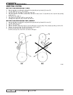
Page 14: ...t is worn replace it Check that the belt tensioner 92 is in good condition Disengage the support rod 60 and close the hood 26 MOTOR TO MAIN BROOM BELT REPLACEMENT Drive the machine on a solid and leve...

Page 15: ...eration is affected and the moving or electrical parts can overheat thus reducing machine life Pay careful attention when performing the above mentioned checks and always use the machine according to...

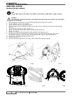
Page 16: ...ators B until the broom is at the maximum distance from the ground Screw down the knobs A On the left side of the machine loosen the knob C Remove the broom lid D by pulling it upwards to disengage th...

Page 17: ...brooms are too worn and can no longer be adjusted replace them according to the procedure shown in the relevant paragraph If the brooms have to be adjusted individually perform the following procedure...

Page 18: ...SWEEPING SYSTEM ENGLISH SERVICE MANUAL 16 146 1965 000 2 2007 02 TerraTM 3700B SIDE BROOM HEIGHT CHECK AND ADJUSTMENT continues A B D C S300809...

Page 19: ...ound and engage the parking brake with the lever 23 Turn the ignition key 2 to 0 and remove it Operating inside the side broom loosen the screw A and then remove the broom with the hub B by disengagin...

Page 20: ...following conditions are required Lower the main broom Lift the side brooms Drive the machine at the maximum speed Clean the vacuum filter by using the filter shaker Drive the machine on a stretch of...

Page 21: ...springs B and remove the four carbon brushes C Check the carbon brushes for wear Replace the carbon brushes when the contact with the motor armature is insufficient the carbon brushes are worn the ca...

Page 22: ...ain motor D from the fusible link I Remove the cable L of the main motor D from the machine frame Remove the three screws M and the nut N then remove the motor reduction unit O and the manual vacuum s...

Page 23: ...ING SYSTEM SERVICE MANUAL ENGLISH TerraTM 3700B 146 1965 000 2 2007 02 21 MAIN MOTOR AND REDUCTION UNIT REMOVAL INSTALLATION continues U V W W T T Y X Z Z AC S S S S M M M O AA AC AC N Q Q Q Q R P S30...

Page 24: ...plate AN Remove the belt 89 from the pulley 94 for an easier removal turn the pulley 94 by manually operating on the fan 73 Remove the three screws M and the nut N then remove the starter dynamo O an...

Page 25: ...SERVICE MANUAL ENGLISH TerraTM 3700B 146 1965 000 2 2007 02 23 STARTER DYNAMO AND REDUCTION UNIT REMOVAL INSTALLATION continues U W W V Z Z AL AG AF AH AI Y X AC S S S T T M M AA O AC N AD AE Q Q Q Q...

Page 26: ...wn in the User Manual The following conditions are required Lift the main broom Lower the side brooms Drive the machine at the maximum speed Clean the vacuum filter by using the filter shaker Drive th...

Page 27: ...s must be removed before tilting the machine otherwise serious damage to people or machine can occur Paying careful attention and with the help of an assistant lift the machine front side I then lean...

Page 28: ...on and with the help of an assistant lift the machine front side A then lean its rear side on the ground as shown in the figure by setting it down carefully on a proper guard B Disconnect the terminal...

Page 29: ...lacement Remove the front cover see the procedure in the relevant paragraph Loosen the mounting screws A of the microswitch B By using the slot C adjust the position of the microswitch B and the relev...

Page 30: ...peration of the main broom drive system remove The main motor carbon brushes are worn replace The main motor is faulty repair or replace The main motor driving belt is broken replace The wiring harnes...

Page 31: ...72 for an easier removal turn the pulley 72 by manually operating on the fan 73 Remove the screws 43 and the right lid 42 together with the belt 71 Adjust the height of the skirt I by using the slots...

Page 32: ...SKIRT ENGLISH SERVICE MANUAL 30 146 1965 000 2 2007 02 TerraTM 3700B SKIRT HEIGHT AND OPERATION CHECK continues M P P N S300248 S300249 S300250 S300251 S300376 S300377...

Page 33: ...e screws D Adjust the side skirt height as shown in the previous paragraph Install the components in the reverse order of removal Right skirt Remove the main broom as shown in the relevant paragraph R...

Page 34: ...able terminal F from the front skirt G CAUTION When lead WET batteries are installed do not tilt the machine for more than 30 from the horizontal plane to prevent the highly corrosive acid from leakin...

Page 35: ...ecessary adjust the front skirt lifting cable as shown below Cable adjustment Remove the hopper 36 as shown in the User Manual Remove the batteries 61 and the battery container CAUTION Batteries must...

Page 36: ...occur Paying careful attention and with the help of an assistant lift the machine front side A then lean its rear side on the ground as shown in the figure by setting it down carefully on a proper gu...

Page 37: ...d air F at maximum 87 psi 6 Bar blowing only from the side protected by the wire gauze E at a minimum distance of 12 in 30 cm see the figure Moreover according to the filter type observe the following...

Page 38: ...y 2 to I and do not press the drive pedal 21 Turn on the filter shaker by pressing the relevant push button 10 and apply an ammeter A on the cable B Check that the electrical input of the filter shake...

Page 39: ...brush connections B Remove the carbon brush mounting screws C Remove the carbon brushes D Check the carbon brushes for wear Replace the carbon brushes when the contact with the motor armature is insuf...

Page 40: ...components in the reverse order of removal TROUBLESHOOTING POOR VACUUMING PERFORMANCE OF THE MANUAL VACUUM SYSTEM Possible causes There are dust or foreign materials slowing down the operation of the...

Page 41: ...t Remove the hopper 36 as shown in the User Manual Remove the batteries 61 and the battery container WARNING Batteries must be removed before tilting the machine otherwise serious damage to people or...

Page 42: ...BRAKE SYSTEM ENGLISH SERVICE MANUAL 40 146 1965 000 2 2007 02 TerraTM 3700B BRAKE ADJUSTMENT for machines up to serial number 062211246 continues B A S300826...

Page 43: ...the following procedure Adjustment Place the machine on a hoisting system if available Otherwise drive the machine on a level ground To keep the machine stationary do not engage the parking brake app...

Page 44: ...chine front side A then lean its rear side on the ground as shown in the figure by setting it down carefully on a proper guard B Remove the clip C from the brake tie rod Remove the fork D from the bra...

Page 45: ...it on two fixed stands in order to keep the front wheel slightly lifted Cut the fastening clamps A Loosen the terminal B and remove the cable C Turn the wheel G manually to take the junction link H o...

Page 46: ...the hood 26 can be closed then perform the test shown in the next step In this way the ammeter C can be seen by the operator seated on the machine Drive system motor electrical input check Start the...

Page 47: ...Replace the carbon brushes when the contact with the motor armature is insufficient the carbon brushes are worn the carbon brush contact surface is not integral the thrust spring is broken etc If nece...

Page 48: ...before tilting the machine otherwise serious damage to people or machine can occur Paying careful attention and with the help of an assistant lift the machine front side A then lean its rear side on...

Page 49: ...rewdriver D loosen the threaded dowel E locking the shaft K of the potentiometer F Lock the actuator G of the microswitch H if equipped to closed position as shown in the figure then check the multime...

Page 50: ...ues TROUBLESHOOTING THE MACHINE DOES NOT MOVE Possible causes The batteries are discharged charge The drive system motor carbon brushes are worn replace The drive system motor is faulty repair replace...

Page 51: ...tilting the machine otherwise serious damage to people or machine can occur Check for Tightening of mounting screws and nuts Correct position of the fasteners Visible faults in the components Disenga...

Page 52: ...lectrical system connections from the panels F and G Lift the lever F by disengaging the pins G from the housings H Remove the terminal I of the cable J from the housing of the lever F Insert the cabl...

Page 53: ...EM SERVICE MANUAL ENGLISH TerraTM 3700B 146 1965 000 2 2007 02 51 FRONT COVER DISASSEMBLY ASSEMBLY for machines from serial number 062211247 continues S R C F G H K J I L I J P O M N Q K R E D F G E A...

Page 54: ...ING LEVER REPLACEMENT for machines from serial number 062211247 Disassembly Remove the front cover see the procedure in the relevant paragraph Disconnect the steering column tilting adjusting lever A...

Page 55: ...or 63 Disconnect the terminals and remove the batteries 61 Battery installation According to the type of batteries WET or GEL set the machine electronic board and the battery charger according to the...

Page 56: ...e ignition key 2 to 0 and remove it Open the hood 26 and engage the hood support rod 60 Disconnect the battery connector 63 Remove the screws B then move the fuse panel A carefully Disconnect the conn...

Page 57: ...nnectors E for lead batteries or on GEL connectors F for gel batteries NON START FUNCTION CHECK WITHOUT OPERATOR ON THE DRIVER S SEAT When the machine is off and the operator is not on the driver s se...

Page 58: ...shaker motor fuse 25 A F2 Manual vacuum system fuse 40 A optional F3 Horn and pivoting light fuse 10 A optional F4 Working light fuse 10 A optional F5 Side broom motor fuse 10 A F6 Horn HN1 Key K1 Wor...

Page 59: ...ELECTRICAL SYSTEM SERVICE MANUAL ENGLISH TerraTM 3700B 146 1965 000 2 2007 02 57 COMPONENT LAYOUT continues 32 21 29 6 39 38 9 33 30 26 22 24 27 20 3 34 25 8 10 11 2 35 36 S300839...

Page 60: ...ELECTRICAL SYSTEM ENGLISH SERVICE MANUAL 58 146 1965 000 2 2007 02 TerraTM 3700B COMPONENT LAYOUT continues 7 28 23 37 12 13 31 14 15 16 17 18 19 4 1 5 12a S300840...

Page 61: ...m system fuse 40 A optional F4 Horn and pivoting light fuse 10 A optional F5 Working light fuse 10 A optional F6 Side broom motor fuse 10 A HN1 Horn K1 Key L1 Working light optional M1 Main broom moto...

Page 62: ...5 30 RD SWS BU PK BK BE1 SW7 GY ES3 SW6 ES1 inst stab EB1 BK L1 GY F5 BK M4 BK M5 SW5 F6 EB2 M1 M2 B B FT BK M2 BK M3 ES2 VT F2 R1 SW2 BK M6 ES3 BN F3 BZ1 BU RD RD WH OG OG BUBK BN WHRD RD BU RD RD VT...

Page 63: ...ELECTRICAL SYSTEM SERVICE MANUAL ENGLISH TerraTM 3700B 146 1965 000 2 2007 02 61...

Page 64: ...Nilfisk Advance Inc 14600 21st Avenue North Plymouth MN 55447 3408 www nilfisk advance com Phone 800 989 2235 Fax 800 989 6566 2007 Nilfisk Advance Inc Plymouth MN 55447 3408 Printed in Italy...

Reviews: