background image


AF-5000 

Pilot’s Guide


Experimental instrument limited to use in experimental aircraft. 

Not approved for use in aircraft with FAA type certificates.


Patents 6,271,769 B1 and 6,940,425


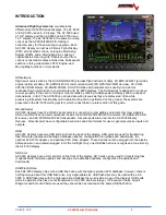
Summary of Contents for AF-5400

Page 1: ...AF 5000 Pilot s Guide Experimental instrument limited to use in experimental aircraft Not approved for use in aircraft with FAA type certificates Patents 6 271 769 B1 and 6 940 425...

Page 2: ...tery and are correct Applying Power for the First Time Turn on aircraft Master Switch power and power on the screens Verify the unit powers on Configure Advanced SV Network on PFD EFIS o SET CAL 2 Adv...

Page 3: ...urer Magnetometer Alignment completed on all screens with an ADAHRS installed EFIS AOA Calibration Checklist completed Pitot Static check completed from an authorized FAA Repair Station EFIS and autop...

Page 4: ...ion of the monitoring system Keep the operating manual in the aircraft at all times 5 AFS is not responsible for shipping charges or damages incurred during shipment 6 No one is authorized to assume a...

Page 5: ...400 Interface 23 Touch Screen 25 Altitude 26 Barometric Pressure Altitude 26 Airspeed 26 Horizon Roll and Pitch 26 Heading EFIS DG 27 Wind Display 27 Skid Slip Ball Inclinometer 28 Standard Rate Turn...

Page 6: ...nel Controls 71 Com Radio Control 72 Transponder Control 75 Remote Audio Panel Control 76 Moving Map Display 80 Map Features 80 Map Options 81 Zoom Range 82 Map Panning Pointer 82 Remote EFIS Joystick...

Page 7: ...el Computer Modes 109 Power Display 110 EGT CHT Display Modes 111 EFIS Checklists 112 Maintenance Log 114 Weight Balance Screen 115 EFIS Data Logs 116 APPENDIX A AF 5000 IFR Procedures _______________...

Page 8: ...0 7 11 2013 Added P N 72102 GPS Module 2 11 8 23 13 CHT EGT Wiring Coolant Temp 2 12 8 28 13 GTN650 Interface Trouble Shooting 2 14 9 7 13 Added AFS ADS B Install New GTN650 Configuration 2 15 9 20 13...

Page 9: ...cribed in a later section of this guide RS 232 Serial AF 5000 displays have five RS 232 serial ports for connection to compatible equipment SkyView modules which use RS 232 serial communications inclu...

Page 10: ...ted Synthetic Vision Synthetic Vision displays the terrain directly ahead of the aircraft Terrain is graphically represented in sectional chart color variations which represent topographical elevation...

Page 11: ...ms Both modules are powered by the AF 5000 display and thus will provide position updates when the AF 5000 display is operating on battery backup power Each module outputs GPS data to AF 5000 in NMEA...

Page 12: ...ed VHF Com Radio for AF 5000 consisting of two modules the SV COM PANEL and the SV COM 425 The SV COM C25 has 25 kHz channel spacing and is intended primarily for aircraft operating in the US The SV C...

Page 13: ...on USB Jacks one per display SV INTERCOM 2S o Copilot Push To Talk PTT Button Likely integrated into the stick o Copilot Headset Jacks o Music In Jack o Pilot Push To Talk PTT Button Likely integrated...

Page 14: ...rt a 30 second countdown to power off and display an on screen alert as long as there is no airspeed or RPM Pressing any button will bypass the countdown and the display will remain powered on Care sh...

Page 15: ...ob is controlling the Heading Bug To make the knob control the CDI course OBS you would first push the CRS button and the knob flag would point to CRS You can also type a value instead of using the kn...

Page 16: ...r of the EFIS DG HIS Gray White G RESET Resets the G Meter AOA CAL Enter AOA Calibration Mode SOURCE Sets the GPS source for the SVN display GNAV1 GPS2 AUTO The Dynon GPS 250 or GPS 2020 have higher a...

Page 17: ...u DIM Dims the displays in the Aircraft BARO Enables you to adjust the Baro while doing the Checklist PAGE Selects the Checklist Page CLR Clears the Checklist items Bottom Buttons RADIO Brings up the...

Page 18: ...Hardware Reboot The display CPU can be rebooted by pressing and holding Button 1 and Knob 1 for 40 seconds This causes the internal hardware to reboot and reinitialize the system This should only be...

Page 19: ...ons available for each item that pop up when the button is pressed The button layout is configured so that a double press of the button always changes the item from OFF to ON or ON to OFF for simplifi...

Page 20: ...gine view will change to no engine view A single finger swipe in the upward direction will cause a screen in full EFIS view to bring up half engine view A screen in half engine view will change to ful...

Page 21: ...Audio ON or OFF PITCH ADJ Selects EFIS Horizon pitch adjust setting to compensate for panel tilt ENGINE Button Options ENGINE Turns the ENGINE display ON OFF Turns the ENGINE display OFF OAT F C Sele...

Page 22: ...Requires optional data subscription OFF Turns the MAP display OFF MAP Displays the standard MAP screen SECTION Display the VFR Sectional Requires optional data subscription IFR LOW Display the IFR Lo...

Page 23: ...screen Screen Selection Screen Selection is done through touch screen gestures A single figure drag motion will turn on or off different displays in the same manner as touch screen equipped AF 5000 E...

Page 24: ...wist knob to scroll through Menus 3 Press Knob again to set new function Access the SET Menus Calibration Page on 5400 Display 1 Tap SET 2 The SET categories EFIS ENGINE will be displayed across the b...

Page 25: ...drags and pinches Areas boxed in yellow recognize a tap input to adjust parameters and as a shortcut to menus For instance a tap of the Transponder Status tab in the top left will bring up the transpo...

Page 26: ...he altitude should be correct after a power cycle Airspeed The airspeed is displayed on the left side of the screen using an analog 4 color tape and digital readout The airspeed range marks can be adj...

Page 27: ...direction the aircraft nose is pointed GPS Ground Track direction the aircraft is moving over the ground The difference between Heading and Ground track is due to wind or magnetic interference Wind Di...

Page 28: ...f the yellow bank angle pointer is aligned with one of the white triangles a 180 turn will be completed in 1 minute The required bank angle will change with airspeed and the triangles will disappear b...

Page 29: ...t inset window SET EFIS G METER The Dynon ADAHRS G Meter is limited to 10 8 G s and will record the maximum and minimum G s that the aircraft has seen since the last time the G RESET button was presse...

Page 30: ...ould press the knob button until it appears Holding the knob down for two seconds will sync the altitude bug to the current altitude The box on the top of the altitude tape shows the current bug locat...

Page 31: ...led IAS will set the desired airspeed bug location Holding the knob down for two seconds will sync the airspeed bug to the current airspeed The box on the top of the airspeed tape shows the current bu...

Page 32: ...T STOP Starts the Timer or Stops the Timer CLOCK MODE AM PM 24H Zulu NET SYNC Forces all screens to the same time OFFSET Sets the Zulu offset SEC Adjusts the timer seconds MIN Adjusts the timer minute...

Page 33: ...displayed on the center of the screen You can select the ADAHRS that the system is using from the OPTIONS MENU Touch the center of the PFD display Selecting an ADAHRS on the Pilot PFD EFIS screen wil...

Page 34: ...ther the flap position sensor for the screen or the supplied switch connected to Input 3 on the main EFIS harness The AOA Use Flap Angle Sensor Found in the AOA menu in Instrument Calibration should b...

Page 35: ...U ARE NOW IN THE FLIGHT MODE LANDING CONFIGURATION CALIBRATION AIRCRAFT LOCATION AIRBORNE FLAPS GEAR CONFIRMED DOWN EFIS AOA DISPLAY ON ON AOA CAL Button PUSH RELEASE CONFIRM flap down calibrate page...

Page 36: ...Version 15 0 AF 5000 Series Pilot Guide 36 Analog Instrument Page EFIS ANALOG AF 5400 SET EFIS ANALOG...

Page 37: ...off power to the EFIS it should switch to the backup battery for 30 seconds and bring up a warning that it is about to shut down If you press any button during the shutdown warning it will continue to...

Page 38: ...ttempting to fly in IMC The biggest change new SVN users will notice is the lack of a definite horizon like a standard attitude indicator Attitude indicators traditionally represent level flight when...

Page 39: ...e pilot alert of altitudes that could result in Controlled Flight into Terrain CFIT Terrain is shaded in yellow or red based on the altitude of the aircraft and the altitude of the terrain below When...

Page 40: ...tic Vision feature 2 Altitude Source Source for SVN should be auto 3 Terrain Warnings ON OFF Enables Disables terrain shading based on altitude 4 TAWS Airspeed Shutoff KTS Airspeed that the terrain wa...

Page 41: ...e drawn at half of their height There are several exclusions users will want to be aware of Obstacles beyond 18nm are not shown Obstacles less than 1000ft AGL are not shown beyond 6nm Obstacles more t...

Page 42: ...p Page display of traffic See the Traffic section in the MAP and VFR GPS Navigator Operation section for complete descriptions of the types of targets that may be shown Unlike the Map Page display how...

Page 43: ...a higher or lower altitude ALL of the HITS boxes will move up or down to the altitude A climbing or descending path will not be displayed Enabling Disabling HITS Press EFIS HITS ON OFF Flying with HI...

Page 44: ...ets the G Meter Maximum and pointers to 1 G CRS SELECT Selects the current CDI needle source BRG SELECT Selects the current BRG needle source Inset Windows Let s you display a small inset window on th...

Page 45: ...ide 45 Display Configuration Menu You select the display setup menu by pressing the DISP button from the EFIS main menu or by pressing the back arrow icon The Display Menu controls how the screen is s...

Page 46: ...GPS and a GREEN needle is always VOR LOC The source label will indicate the radio type Label Radio Type GPSNAV1 GPSNAV2 GPS NAV IFD540 IFD440 GTN 650 750 NAV1 NAV2 GNC 255 SL 30 NAV COM GPS1 GPS2 GPS...

Page 47: ...OURCE Selects the needle source GNAV1 GPS Navigator GPS2 Backup GPS INTFP Internal Flight Plan MODE The normal setting should be AUTO and let the IFD or GTN select the CDI source This will enable the...

Page 48: ...to the current course selected on the GPS CDI Course Deviation Indicator The GPS CDI scale should be automatically set by the remote WAAS radio using the ARINC data line TRK Track The current GPS trac...

Page 49: ...ator indicates 2 degrees of deviation from the course radial VOR If the radio is tuned to a standard VOR frequency and is giving a valid TO FROM indication the display will show VOR in green letters I...

Page 50: ...not have a valid glideslope it will display GS in red and it should not be used for navigation BC If the NAV radio is tuned to a localizer and is in Back Course mode BC will be displayed in green NOT...

Page 51: ...Pro Pilot The autopilot and flight director are very closely connected and are controlled from the same source The aircraft should closely follow the flight director when the autopilot is receiving c...

Page 52: ...CDI Needle The Touch screen NAV button will be yellow indicating it is in ARM mode As soon as the Heading is within 30 deg of the coarse and the CDI needle is within 80 it will switch to NAV mode NAV...

Page 53: ...get the autopilot to change altitude IAS Climbing Considerations If you are trying to climb and the aircraft is already at the airspeed bug you will need to increase power or lower the airspeed bug to...

Page 54: ...waypoint does not have an altitude set it will continue to follow the Altitude Bug The autopilot will not descend below the Altitude Bug the EFIS will prompt you if you need to lower the Altitude Bug...

Page 55: ...heading holds and turns This procedure should be performed with the autopilot roll axis in track TRK ALT mode where the purpose of the autopilot is to keep the aircraft s GPS ground track aligned wit...

Page 56: ...ot cannot keep up with the flight director roll command bar ROLL SENSITIVITY should be increased At some point the AP will track the command bars but follow behind them ROLL GAIN will reduce the gap C...

Page 57: ...y 10 knots and observe the results The AP should promptly change pitch to change speed and smoothly reach the commanded speed with little or no overshoot above the target if increasing below the targe...

Page 58: ...Version 15 0 AF 5000 Series Pilot Guide 58 Flowchart Pitch Axis IAS Hold Procedure...

Page 59: ...d but distinct parts of the autopilot The Altitude Hold Procedure which follows will address common problems and once those are resolved direct you to the Altitude Capture Procedure which will tune yo...

Page 60: ...Version 15 0 AF 5000 Series Pilot Guide 60 Altitude Capture Procedure Part 1 of 2 Part 2 of 2...

Page 61: ...or pushing G to oppose G generated by air pockets The amount of G the autopilot will apply is limited by G ERROR LIMIT If for example you encounter a 0 5 G updraft and G ERROR LIMIT is set to 0 25 th...

Page 62: ...Version 15 0 AF 5000 Series Pilot Guide 62 Autopilot Settings Defaults...

Page 63: ...re color coded based on the command source The wing bar color will show the horizontal steering source and the triangle tip color shows the vertical steering source Gray No Source Red Source Flagged Y...

Page 64: ...EFIS AP Settings when using a Trutrak Autopilot LATERAL EFIS Autopilot Control Settings ROLL GAIN 05 Range 01 2 0 The LAT Gain setting controls how fast the aircraft will respond to errors in track or...

Page 65: ...trols in the CAL Autopilot menu the joystick can also be used as a shortcut LEFT and RIGHT cycle between Lateral modes while UP and DOWN cycle through Vertical modes Moving the joystick to the left fo...

Page 66: ...touch a tab to select it or use the joystick to move between tabs System MAP Weather Transponder GPS SYS Information Displays the system Serial Number software version information IP address MAP Infor...

Page 67: ...0 AF 5000 Series Pilot Guide 67 WX Information The WX information page contains information and diagnostics for any installed XM or ADS B receiver XM Weather Information USA and Canada ADSB Weather I...

Page 68: ...F 5000 Series Pilot Guide 68 Transponder Information The XPNDR information page contains information about the Transponder GPS Information The GPS information page contains information about the attac...

Page 69: ...ic Circuit Breaker Page The Electronic Circuit Breaker menu gives you the ability to see the current state of each electronic circuit breaker and reset any of the tripped breakers You can also turn ON...

Page 70: ...o do the following Transfer Maintenance file to the USB or SD card SET CAL Admin Settings Transfer Maint Save Edit file with a PC text editor Transfer Maintenance file from the USB or SD card SET CAL...

Page 71: ...ponder controls Press COM for the Comm radio controls Transponder Code Standby Radio Frequency Transponder Mode Active Radio Frequen You can remotely tune the Comm Radio or Transponder from any EFIS s...

Page 72: ...tick or touching the tab COM Tab GND Selects the Ground Freq TWR Selects the Tower Freq VOL Adjust Volume if supported XFR Transfer Primary and Standby Frequencies Keyboard Type frequency number using...

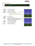
Page 73: ...Version 15 0 AF 5000 Series Pilot Guide 73 FREQ Tab RCNT Tab...

Page 74: ...type for example busy airports may have multiple tower frequencies TWR Tunes tower Unicom and Multicom frequencies ATIS Tunes ATIS and other weather information frequencies including AWOS ASOS AWIB a...

Page 75: ...e remote transponder has the following controls AUTO Turns transponder mode to Automatic ON Turns Transponder ON with no Altitude reporting STBY Sets Transponder to Standby Mode ALT Turns transponder...

Page 76: ...e Radios On screen touch or hardware buttons can be used to select one of the communication transceivers for the pilot and copilot position and allows radio transmission In Split Mode the PDA360EX R h...

Page 77: ...selection of the three intercom modes The description of the intercom mode function is valid only when the unit is not in the Split mode Then the pilot and copilot intercom is controlled by the ICS b...

Page 78: ...e systems such as portable cellular phones with Bluetooth connectivity Warning United States FCC Regulations contained in 47 CFR 22 925 currently contain prohibition on airborne operation of cellular...

Page 79: ...ait for the message to finish playing before accessing the prior message or cancel the current playback and step backward To cancel the playback press and hold the COM receive playback button for two...

Page 80: ...ource Map Features Currently the map will display the following features 1 Public and Private airports 2 Airspace 3 Intersections VOR s 4 Obstructions 5 State Lines 6 Rivers 7 Major Roads The MAP page...

Page 81: ...llowing Map features can be turned ON or OFF TERRAIN Map Terrain PRIVATE Private Airports INTSECT Intersections AIRDATA Airspeed and Altitude Tape Map Scale Option KTS NM Knots KPH KM Kilometers MPH S...

Page 82: ...This can be accomplished through the joystick by dragging it in the direction of travel anytime RNGE is active a map pointer will be displayed allowing you to make selections on the map Pushing in on...

Page 83: ...oes not have a map displayed you can use the joystick to control the remote EFIS screen map If the PFD does have a map displayed the joystick will control the local map You need to configure the MFD E...

Page 84: ...ressing the INFO button will display the information for the highlighted airport CAUTION To see the actual closest airports zoom in before pressing the NRST button Direct To Navigation Pressing the D...

Page 85: ...fter pressing the NRST button it changes to the EMERGENCY button i e Double Tap NRST Pressing this button will bring up a list off all airports that are within engine out gliding range You need to con...

Page 86: ...s and airport information The pages are selected by dragging the joystick in the direction of the desired page Airspace Airspace is displayed on the moving map Airspace Information including the verti...

Page 87: ...s and Approach Plates can be done through a simple selection of the MAP Button which will then bring up the menu to select the desired database chart Selection through the Touch Screen is done by tapp...

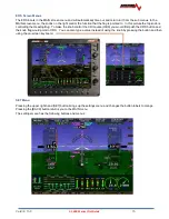
Page 88: ...Version 15 0 AF 5000 Series Pilot Guide 88 VFR Sectional Full Screen Mode Split Screen Mode...

Page 89: ...Version 15 0 AF 5000 Series Pilot Guide 89 IFR Low Altitude Chart Airport Diagrams...

Page 90: ...approach plates are geo referenced and will display current aircraft position if on the approach plate area If a traffic receiver is installed traffic should be displayed on the approach plate If the...

Page 91: ...nherent delays and relative age of the WX data can be experienced NEXRAD weather cannot be used for short term weather avoidance NEXRAD High resolution radar image of radar reflectivity and lighting s...

Page 92: ...t to the airport on the map page In additional there will be a TAF button on the airports info page TAF s are given in their original coding TFR s Active TFR s are drawn in RED and future TFR s are YE...

Page 93: ...ft are displayed over the map page using standard NOAA barbed symbols To change the altitude press MAP WX and use the joystick to select Flight Level Altitudes are given in Flight Levels i e FL120 is...

Page 94: ...Selecting the WX Tab The age of the displayed XM data Mode Screen MASTER or SLAVE Receiver Radio ID Number Required when calling XM Activation 1 800 985 9200 Antenna Indicates whether or not an XM ant...

Page 95: ...indicated on the display In extreme cases this can mean that the images you see on the map may be 15 20 minutes older than the age indicated See http www ntsb gov doclib safetyalerts SA_017 pdf for f...

Page 96: ...ayed on the upper left hand corner of the map REGNL is the local high resolution data and CONUS is the low resolution data for the continental US The EFIS ABOUT WX page displays pertinent information...

Page 97: ...es both the device that is currently providing traffic and the status of the traffic receiver Possible devices and their possible states include ADS B Any ADS B source such as the SV ADSB OK Signifies...

Page 98: ...ck or SD card to update the files The database files for the United States are updated every 28 days and provided for no charge on the www Advanced Flight Systems com web site The optional VFR Section...

Page 99: ...ribed distance from the waypoint at above below the set altitude SRC XXX Selects the GPS source for the internal flight plan GNAV1 GNAV2 GPS1 GPS2 CHART Displays the approach plate if installed on the...

Page 100: ...This is useful when ATC gives an amended clearance and time is needed to modify the flight plan Vertical Navigation using the internal Flight Plan Using the internal flight plan the EFIS can descend t...

Page 101: ...To configure the Wi Fi Adapter access the SET CAL MENU The AF 5000 system supports both HOST and CLIENT Modes HOST Mode Use Host mode if you want the EFIS to connect to an iPad or iPhone running a fl...

Page 102: ...l port that is configured for ADS B data on the same EFIS as the Wi Fi module Selecting a Wi Fi ADS B receiver or Wi Fi Hotspot You can select the Wi Fi network to connect to from the SET WiFi button...

Page 103: ...ight app This feature requires one Wi Fi Adapter in the aircraft If the Wi Fi module is installed in the same EFIS that is wired to an ADS B receiver it will also send ADS B weather and traffic data t...

Page 104: ...S Flight Planning page and Moving Map The EFIS CDI source Flight Plan must be set to Internal to accept a flight plan from ForeFlight Figure ForeFlight Flight Plan To send the flight plan first ensure...

Page 105: ...explicit action by the pilot GPS and Attitude on ForeFlight Once the AF 5000 EFIS is connected to ForeFlight it will also send its GPS position to the app The GPS position sent by the EFIS is only usa...

Page 106: ...ort and Arrival Airport To Export Logbook data from your AF 5000 insert a SD Card and press SET LOGS LOGBOOK This information is easily imported to LogbookPro on your personal computer The file stored...

Page 107: ...ach to any airport in the map database or user airport data file with runway endpoint data The flight plan menu lets you select the runway and set the glideslope Once you enter a glideslope the system...

Page 108: ...ify the calibration of the system over many tanks of fuel before using the GALS REM and or GALS USED Modes as an indication of the fuel in the tanks or fuel used Even after verifying the calibration o...

Page 109: ...fuel flow and the GPS ground speed If power setting is changed or the winds change the fuel computer will not be correct NM GAL Nautical Miles per Gallon Displays the current ground distance traveled...

Page 110: ...and using the keypad or rotating the joystick for the correct amount and then pressing the FC SET button Power Display The system will display the estimated Power and the current RICH PEAK LEAN Statu...

Page 111: ...e leaning peak detection mode is selected from the main screen by pressing the ENGINE PEAK As the engine is leaned the EGT bars for all cylinders will rise As each cylinder reaches peak EGT a tattleta...

Page 112: ...can be modified using Microsoft Word Pad on a PC Lines are limited to 96 char long DO NOT USE COMMAS IN THE CHECKLIST TEXT CHKLST0 TITLE BEFORE STARTING ENGINE CHKLST0 LINE1 Preflight Complete CHKLST0...

Page 113: ...INE7 Fuel Selector Valve DESIRED TANK CHKLST2 LINE8 Mixture RICH below 3000ft CHKLST2 LINE9 Elevator and Aileron Trim NEUTRAL CHKLST2 LINE10 Throttle 1800 RPM CHKLST2 LINE11 Magnetos CHECK 175 max dro...

Page 114: ...dified using Microsoft Word Pad on a PC Units must be Tach hours or days DESC Annual Inspection LASTDATE 08 05 2006 LASTTACH 210 80 INTERVAL 250 UNITS tach hours NEXTLINE 0 DESC Tires LASTDATE 04 05 2...

Page 115: ...s REST to copy the file back to the EFIS from the SD Card The normal weight balance settings can be adjusted on the Weight Balance page by pressing the STATIONS button The QTY and ARM of the station c...

Page 116: ...e data from last 5 hours 1 hz 10 HRS Flight and Engine data from last 10 hours 1 hz 20 HRS Flight and Engine data from last 20 hours 1 hz ALL Flight and Engine data all saved data 1 hz Importing Fligh...

Page 117: ...Version 15 0 AF 5000 Series Pilot Guide 117 Using Savvy Analysis to display the recorded Flight Data https www savvyanalysis com The AF 5000 recorded Flight Data is compatible with Savvy Analysis...

Page 118: ...t CVO is magenta notice the flight plan has been automatically transferred to the AF 5000 EFIS GNAV1 GPS Navigator 1 flight plan Touch the AP Status Bar to bring up the Autopilot Menu Autopilot is Eng...

Page 119: ...the IFD540 s lateral GPS course and is holding altitude at the altitude bug until vertical guidance is provided from the IFD540 usually just outside the FAF Notice all the flight plan legs including t...

Page 120: ...nd ARM for vertical the autopilot is following the GNAV1 flight plan for lateral and using the altitude bug for vertical We have also set the Minimums bug SET MINA middle knob to 450ft From the approa...

Page 121: ...ot fly below the Minimums Altitude bug Before reaching the decision height we have set the Altitude bug to the 4000ft missed procedure altitude from the approach plate After pressing the SUSP button o...

Page 122: ...nd provided free of charge on the www Advanced Flight Systems com web site Every 28 days you should download the new map data from the support section of our web site www dynonavionics com af 5000 dat...

Page 123: ...EFIS to install the map data from the SET CAL ADMIN Settings DATA Transfer Upgrade Maps AF 5000 High Resolution Terrain DATA The AF 5000 EFIS must have a USB Memory Stick plugged into the back of the...

Page 124: ...in your aircraft This memory stick also contains the Synthetic Vision high resolution data files in the HRTERRAIN folder ChartData subscriptions along with the download manager needed to obtain charts...

Page 125: ...elected the longer the process will take Select the areas that you want to view on the display Again the more items selected the longer the process will take Once finished click OK Once selected press...

Page 126: ...d onto the USB flash drive Click Yes to update the USB flash drive and wait for the update process to complete ALL green lights next to your checked items indicates your device is READY If not click U...

Reviews: