background image


NASA Mars Rover Kit Assembly Instructions 

© Advanced Methods in Innovation, 2017 


Assembly Instructions for  

NASA / INVENTORcloud Mars Rover Kit 

“Gaining Traction on Mars”  


© Advanced Methods in Innovation, 2017 


Summary of Contents for NASA/INVENTORcloud Mars Rover Kit Gaining Traction on Mars

Page 1: ...NASA Mars Rover Kit Assembly Instructions Advanced Methods in Innovation 2017 1 Assembly Instructions for NASA INVENTORcloud Mars Rover Kit Gaining Traction on Mars Advanced Methods in Innovation 2017 ...

Page 2: ... Instructions Advanced Methods in Innovation 2017 2 A What s In the Box The rover kit is contained in a small cardboard box shown below Rover kit components are packaged in the box as shown Rover Kit Box Closed Rover Kit Box Open ...

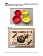
Page 3: ...NASA Mars Rover Kit Assembly Instructions Advanced Methods in Innovation 2017 3 Components found in the rover kit box are as follows Wheels x4 Gearbox Package Rover Wheels Gearbox Package ...

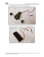
Page 4: ...ructions Advanced Methods in Innovation 2017 4 o Pre wired Gearbox with Pinion Gears Inside Gearbox Package o Battery Pack for AAA Batteries with On Off Switch Inside Gearbox Package Gearbox Pinion Gears AAA Battery Pack On Off Switch ...

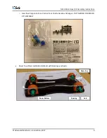
Page 5: ...ructions Advanced Methods in Innovation 2017 5 o Gearbox Components and Instructions Inside Gearbox Package NOT NEEDED FOR ROVER KIT ASSEMBLY Rover Top Clear and Bottom Black with Bearings and Axles Rover Top Rover Bottom Bearing Axle ...

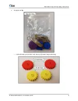
Page 6: ...ASA Mars Rover Kit Assembly Instructions Advanced Methods in Innovation 2017 6 Components Bag o 18 Tooth Gears x2 and 24 Tooth Gears x2 Inside Components Bag Components Bag 24 Tooth Gears 18 Tooth Gears ...

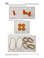
Page 7: ...ds in Innovation 2017 7 o H Bracket and Support Post Inside Components Bag o Wheel Washers x4 Inside Components Bag o Rubber Bands 3 5 x 3 4 x4 7 x 1 8 x2 Inside Components Bag Support Post H Bracket Wheel Washers 7 x 1 8 Rubber Bands 3 5 x 3 4 Rubber Bands ...

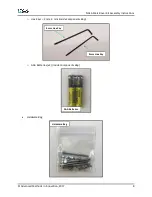
Page 8: ...r Kit Assembly Instructions Advanced Methods in Innovation 2017 8 o Hex Keys 3 mm 4 mm Inside Components Bag o AAA Batteries x2 Inside Components Bag Hardware Bag 4 mm Hex Key 3 mm Hex Key AAA Batteries Hardware Bag ...

Page 9: ...vation 2017 9 o Socket Head Cap Screws M4 x 50 x6 M4 x 10 x2 M3 x 10 x2 Inside Hardware Bag o M4 Wing Nuts x2 M3 Wing Nuts x2 M4 Washers x2 Inside Hardware Bag NASA Decals x2 M4 x 50 Screws M4 x 10 Screws M3 x 10 Screws M3 Wing Nuts M4 Wing Nuts M4 Washers NASA Decals ...

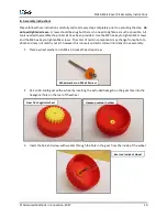
Page 10: ...M3 screws and the M4 hex key to tighten M4 screws The color of certain components may change from photo to photo and may not match your kit however this is purely cosmetic and will not impact rove assembly 1 Place a wheel washer on an M4 x 50 socket head cap screw 2 Pair an 18 tooth gear with a wheel by inserting the extruded hexagon on the gear face into the hexagonal hole on the rear of the whee...

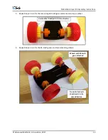
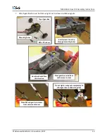
Page 11: ...er bottom Place bottom on table with slots on right Attach wheels with 18 tooth gears on left Attach wheel so that tread points to left Insert M3 hex key in hole on axle to prevent axle from rotating Tighten screw with M4 hex key Do not over tighten Ensure hexagon on gear remains seated in wheel and gear sits flush against wheel ...

Page 12: ... Repeat Steps 1 to 4 for the remaining 18 tooth gear and same color rover wheel 6 Repeat Steps 1 to 5 for the 24 tooth gears and two remaining wheels Verify wheel tread points in this direction Wheels with 24 tooth gears attached Tread of all wheels should point in the same direction ...

Page 13: ...3 x 10 screws and M3 wingnuts Top of gearbox Mounting holes M3 x 10 screws Insert screws from top through mounting holes Place gearbox on bottom with screws in slots Gearbox should face this direction Place M3 wingnuts on screws from underneath rover Do not tighten wingnuts completely to allow gearbox to slide along slots ...

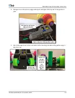
Page 14: ...ighten M3 wingnuts to lock gearbox in place 9 Attach the support post to the rover bottom at the mounting hole behind the gearbox using an M4 x 10 screw Slide gearbox until pinions engage wheel gears Tighten wingnuts to lock gearbox in place Support post mounting hole Insert screw through bottom of rover and into support post and tighten ...

Page 15: ... H bracket to the rover bottom at the two mounting holes on the end of the rover using two M4 x 50 screws Make sure switch is set to OFF Insert batteries and close lid H bracket mounting holes TOP text up and facing direction shown Insert screws from bottom Do not yet tighten screws completely bracket should be able to lift slightly ...

Page 16: ... 13 Place rover top on rover assembly Tighten screws to lock battery holder in place Slide battery pack under H bracket with switch oriented as shown Pull ends of wires through large hole on rover top Screws pass through holes on end of top Orient the rover top as shown INVENT3D sticker not pictured should be facing up ...

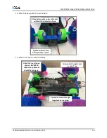
Page 17: ...rt post using an M4 x 10 screw 15 Connect wires to M4 x 50 screws that protrude from the rover top Insert screw from top into support post and tighten Place M4 washers on ends of screws Place ring connectors of both red wires on one of the screws Tighten an M4 wingnut onto the screw to hold connectors in place ...

Page 18: ...the vehicle switching one red wire and one black wire as described in the project documentation will change the vehicle to front wheel drive When the vehicle is in a front wheel drive setting the end of the vehicle with the support post becomes the front and wheel positions should be switched so that tread points in the opposite direction the direction that the vehicle moves Place ring connectors ...

Page 19: ...r insert the M3 hex key through the hole in the rover top closest to the wheel to be removed and into the hole at the end of the axle This will prevent the axle from spinning as the M4 hex key is used to remove the M4 x 50 screw attaching the wheel to the axle Insert hex key through rover top and into hole in axle to prevent axle from rotating ...

Reviews: